QDR
– QTech Digital Radio – Owner’s Manual – v1.4 – October 2014
www.qtech.co.nz
Page 8 of 16
Jumper Settings for Half Duplex RS485 (2-Wire)
Refer to Section 6 for further details on the jumpers
Jumper
Position
JP3
In
JP4
Out
JP5
In
JP6
In
Pinout of RS485 Port when in Half Duplex Mode
QDR
XL4
eXcel
Signal
Input/Output
Description
Pin
Pin
Pin
1
1
1 (NC)
GND
-
Ground
2
2
3
B
Input/Output
Inverting Input/Output
3
3
2
A
Input/Output
Non inverting Input/Output
4
4
4 (NC)
-
-
-
5
5
-
-
-
6
6
GND
-
Ground
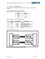
Typical Half Duplex Connection
Note: Line termination resistors are inside the QDR
120 Ohm
A
B
120 Ohm
A
B


