17
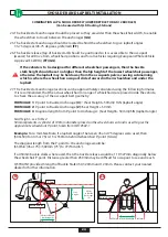
L-TRACK ANCHORAGE AND END CAPS INSTALLATION
OR
8
Parallel
8
Parallel/In-Line
8
Perpendicular
8
Perpendicular/Traverse
BOLTS
TRACK
WOOD FLOOR
VEHICLE FLOOR
WASHER
LOCK NUTS
BOLTS
TRACK
VEHICLE FLOOR
WASHERS
LOCK NUTS
I
J
K
M
• If not using Q’straint hardware, only use minimum Grade 8 bolts (reference ASTM 574 bolt specification) coated in
adequate protection against corrosion per ISO 7253 or ASTM B117
•
Refer to Table 1 - page 11, before installing the track. The track type and orientation varies for different
wheelchair securement systems. Figure I & J show track orientation
IMPORTANT
L
8
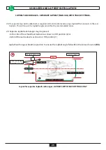
1/2” (13mm) Deep
8
L Track Length
8
1.42” (36mm) Wide
8
Floor
Determine location of Anchorages, refer to
Figure 1 & 2
1. For FLANGE L-TRACK route the floor for each track,
1.42” (36mm) wide x ½” (13mm) deep (K)
2. For END CAPS route an area in the floor for end
caps 1/2” (13mm) deep and 1.42” (36mm) wide with
semi-circular diameter to match End Cap profile (L)
For SURFACE and REGULAR L-track proceed to Step 4.
3. Clean out debris and place track in routed area
4. With track in position, use as template to mark centre
holes to be drilled.
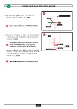
5. Remove track and drill 8mm holes through floor per
drilling pattern. Note: Standard track drilling pattern =
holes every 4” (102mm).
6. Place sealant in floor opening (Flange L-track only)
and reinstall track
7. Pass 8mm bolt through track, vehicle floor, Backing
Plate and Washers (K & M)
Sealant may be used between Backing Plate and floor
if desired.
Recommended Torque=25 FT/LB (47 Nm)


