13
16. After wall construction is complete (including texture and paint), install the Flange
(6)
into the Back Box using six screws
(7)
. Make sure that the
Flange is tight up against the drywall. The Flange will go into the Back Box only one way due to the placement of the screw holes.
17. Optional. Install four screws
(8)
(not supplied) to secure the Flange to the mounting surface.
18. Mount the touchscreen to the Flange. Refer to
“"Mounting the Touchscreen to the Flange" on page 13.
Mounting the Touchscreen to the Flange
This procedure is for mounting the touchscreen to an installed Flange/Back Box assembly.
Refer to
Figure 7
and Packing Lists on
page 10
.
CAUTIONG!:
Be sure the touchscreen is properly supported during this operation. Do
not let the cables support the weight of the unit.
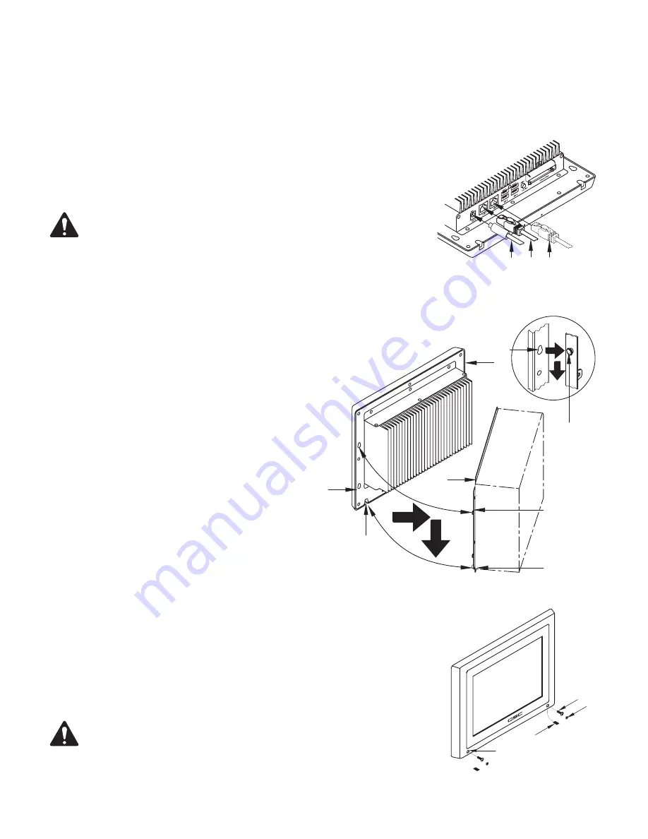
1. Connect the male +12 VDC connector
(1)
from the Power Supply (in the Back Box) to the female
+12 VDC connector on the edge panel of the Q-Sys TSC-8.
2. Connect the data communications cable (male RJ45 plug)
(2)
from the Q-LAN network to the
LAN A receptacle. Ensure that the locking tab on the male RJ45
connector engages with the female RJ45 receptacle on the TSC-8
panel connector.
3. If redundant operation is desired, connect a second data
communications cable into the LAN B receptacle
(3)
on the edge
panel of the Q-Sys TSC-8.
Refer to
Figure 8
.
4. Carefully feed the cables through the Cable Access opening
(Figure 6)
, making sure that the cables are not pinched or in a
position where excess strain is placed on the connectors.
5. Mate the Bezel
(5)
to the Flange
(6)
:
a. Align the Bezel Standoff Slots
(1)
with the Bezel
Mounting Standoffs
(2)
.
b. Place the back of the Bezel
(5)
flat up against the Flange
(6)
.
Make sure the standoffs are inserted into the slots.
c. Slide the Bezel
(5)
down until the Bezel Mounting Standoffs
(2)
are completely engaged with the Bezel Standoff Slots
(1)
.
The Threaded Standoffs
(4)
should be nested in the Bezel
Standoff Slots
(3)
.
Refer to
Figure 9
.
6. Install two screws
(2)
through the Bezel Securing holes
(1)
into the Threaded Standoffs (
Figure 8, 4
).
Do not over tighten.
7. Install two Hole Plugs
(3)
into the Bezel Securing holes
(1)
on the front of the Bezel to hide the
screw holes.
8. Install two Slot Covers
(4)
into the Mounting Standoff Slots on the bottom edge of the touchscreen.
IMPORTANT!:
Before you can use the TSC-8, you must configure the Q-Sys design using
Q-Sys Designer. Refer to the Q-Sys Designer online help for details.
— Figure 7 —
2
3
1
— Figure 8 —
1
2
3
4
5
6
1
2
— Figure 9 —
1
2
3
4
Summary of Contents for Q-SYS TSC-8-BK
Page 19: ......


