background image

Attero Tech by QSC

 unBT2A 

User Manual 


 QSC, LLC 2020 


614-00034 

6 – Bluetooth® Operation 

The unBT2Ais designed for two primary usage modes to facilitate a number 

of professional AV applications. 
 
*

Note: 

Once  paired/connected,  the  Bluetooth®  friendly  name  is  visible  to 

other devices. However, while another device may be able to pair and save 
to its Bluetooth® device list when in this state, breaking the connection of the 

currently active device will not be possible. 
 

Standalone Operation: 

This usage model is intended for applications where casual users of a public 

venue (sports bar, spa, stadium luxury box, fitness center) have access to 
connect their devices to the audio system but headaches are minimized by 

eliminating automatic reconnect and pairing history features. 
 

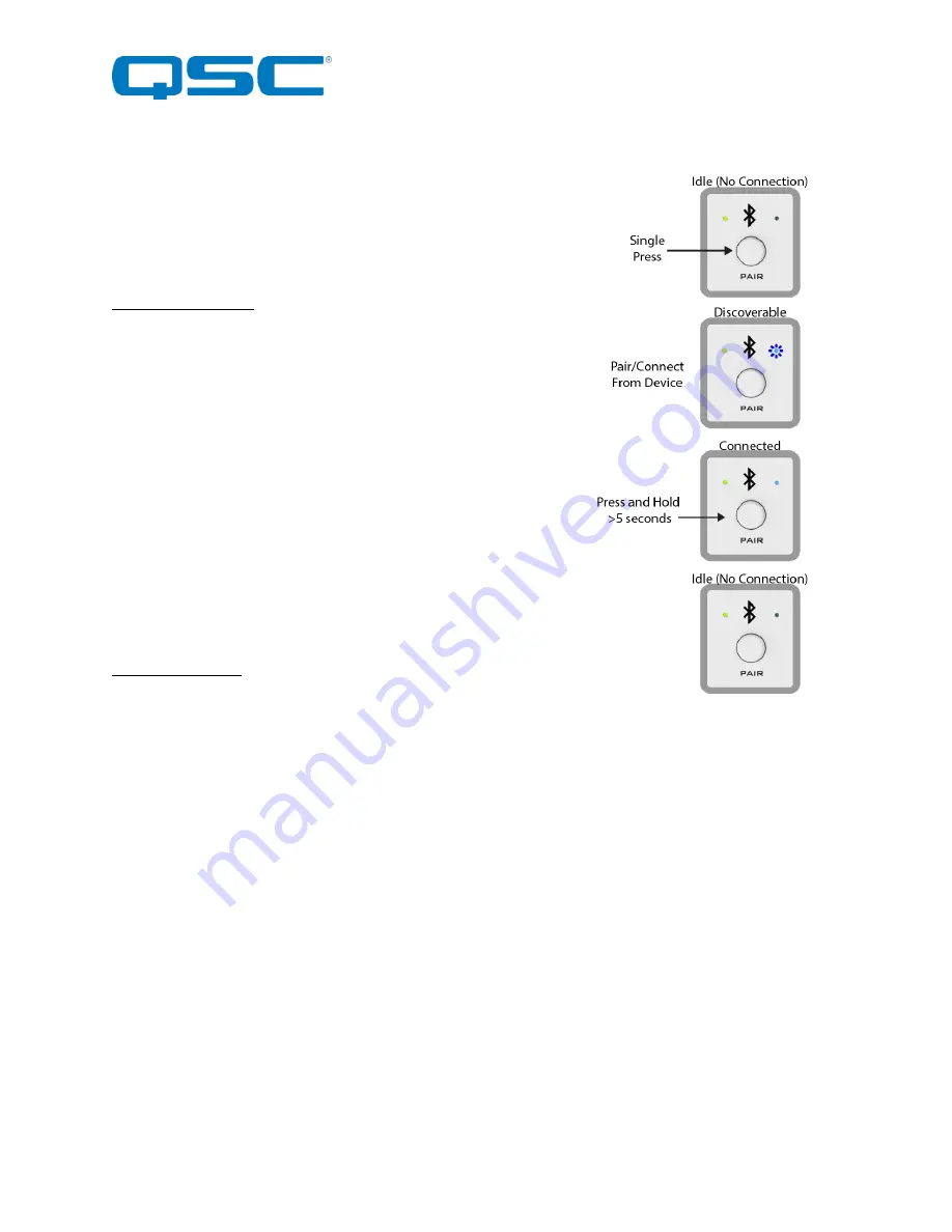
In this mode, users connect their Bluetooth® audio enabled smart device by 
simply  pressing  the  front  panel  “PAIR”  button.  The  blue  Bluetooth®  status 

LED will begin flashing to indicate that the  unBT2A is now visible to other 
Bluetooth®  devices  and  accepting  pairings.  This  pairing  period  lasts  60 

seconds after which the status LED will stop flashing and turn off and the 
unBT2A will disable its Bluetooth® interface. 


*Note: 

The default friendly name visible to other devices is “

unBT2A

”. This 

name  can  be  customized  by  the  installer  using  the  unIFY  Control  Panel 

software (v2.1 or greater). 
 

If a successful pairing is made during the pairing period, the status LED will 
stop flashing and turn constantly on. 

 
To disconnect a device from the unBT2A, press and hold the PAIR button for 

5 seconds and then release it. The status LED will turn off, and the connection 
will be reset. Another device may now be connected by repeating the pairing 

process. 
 

3

rd

 Party Integration: 

In this usage model, the unBT2A is integrated into a large AV system that 

includes a 3

rd

 party control system. Using the RS-232 control port and the 3

rd


party programming API, integrators can customize the usage of the unBT2A. 
The control system the ability to configure the following functions: 

o


Limit errant connections by disabling the front panel control 

o


Implement user privileges by only initiating the pairing/connect process remotely through the control system 

user interface 

o


Report current unBT2A Bluetooth® interface status to the control system 


Figure 9 - Standalone Operation 


Summary of Contents for ATTEROTECH unBT2A

Page 1: ...erved QSC and the QSC logo are registered trademarks of QSC LLC in the U S Patent and Trademark office and other countries All other trademarks are the property of their respective owners Patents may...

Page 2: ...ularly at plugs convenience receptacles and the point where they exit from the apparatus 11 Only use attachments accessories specified by Attero Tech 12 Use only with the cart stand tripod bracket or...

Page 3: ...y energy and if not installed and used in accordance with the instruction manual may cause harmful interference to radio communications Operation of this equipment in a residential area is likely to c...

Page 4: ...uct Features 5 3 System Connectivity 8 4 Initial Device Setup 9 4 1 Factory Reset 9 5 Mounting and Installation 10 5 1 Audio Connections 11 6 Bluetooth Operation 12 7 3rd Party Control 13 7 1 RS 232 I...

Page 5: ...A EXP has an RS 232 port for 3rd party control in installations featuring an integrated control system Features o Single gang Decora form factor for easy installation in space constrained applications...

Page 6: ...cator 3 Power ID Error indicator see note below Note The unBT2A is equipped with error reporting features Upon power up the power LED will initially light red and then change to green if the device bo...

Page 7: ...LLC 2020 614 00034 Figure 2 unBT2A Rear Panel Features 4 USB Configuration Port 5 unBT2A EXP Port CAT5 6 connection for Audio Power and Control Note This is NOT a network port DO NOT connect to a netw...

Page 8: ...re 3 unBT2A EXP Features 7 RJ45 unBT2A Port CAT5 6 connection for Audio Power and Control Note This is NOT a network port DO NOT connect to a network switch 8 Balanced Audio Output Terminal Blocks 9 R...

Page 9: ...this example the analog outputs are interfaced to an audio DSP for processing and distribution throughput the venue The RS 232 is interfaced to a control system to allow extended control over the unBT...

Page 10: ...is powered only via USB If it is necessary to test the audio output while connected to the USB connect the unBT2A EXP and the use the supplied wall wart in order to fully power the device For a comple...

Page 11: ...tionally the unBT2A wall plate should also start up and once ready to operate the front panel power status indicator should also be illuminated green Note Upon power up the power LED will initially li...

Page 12: ...onnecting the outputs of the unBT2A to audio devices GND Pin 1 Pin 3 Pin 2 1 1 2 3 XLR M 2 Wire Cable Shield Or 3 Wire Cable TRS Plug GND Sleeve Tip Ring 2 Wire Cable Shield Or 3 Wire Cable Figure 7 B...

Page 13: ...0 seconds after which the status LED will stop flashing and turn off and the unBT2A will disable its Bluetooth interface Note The default friendly name visible to other devices is unBT2A This name can...

Page 14: ...available to the installer except firmware updates are also supported via the RS 232 interface The full command set that the unBT2A supports can be found in the unIFY 3rd party Software API document a...

Page 15: ...e Maximum audio output level shall be 20dBu in the 4dBu mode and 6dBu in the 10dBVmode The device shall have RS 232 real time control of pairing and other user features over a 3 pin depluggable connec...

Page 16: ...P Profile only Range Approx 10m 30ft minimum Audio Outputs Output Type Two balanced line level with automatic muting on loss of A2DP audio stream Phoenix style 3 81mm de pluggable terminal blocks Outp...

Reviews: