QRP Labs QLG2 Manual Download Page 11

3.6

Status LEDs

Just like it’s predecessor the QLG1,
the QLG2 module has the same
three LED status LEDs. 

In the case of QLG2, these are
0603-size SMD LEDs installed on
the PCB near the GNSS receiver
module. 

LED 1 (red) is the Power LED and is
always lit when QLG2 is powered. 

LED 2 (yellow) is the Serial data
LED and pulses in time with the
serial data. Note that in a departure from the QLG1, this LED is actually OFF during the 
data burst (whereas on QLG1 it is ON during the data burst). The reasons for this are 
explained later, in the circuit explanation section. 

LED 3 (blinding green) is the 1pps indicator and flashes once per second, for 0.1 seconds, 
coincident with the 1pps pulse whose leading edge indicates the exact UT second. This 
LED only starts blinking once a satellite lock (3D fix computation) has been achieved. 

Together, these three LEDs provide an accurate diagnosis of correct operation of the 
QLG2. 

Connecting external LEDs

You may wish to use external LEDs instead of
the onboard ones. For example, you may wish to
make the LEDs visible on the front panel of your
equipment. After all, which of us does not like
blinking lights on his equipment, and generally
the more the merrier. 

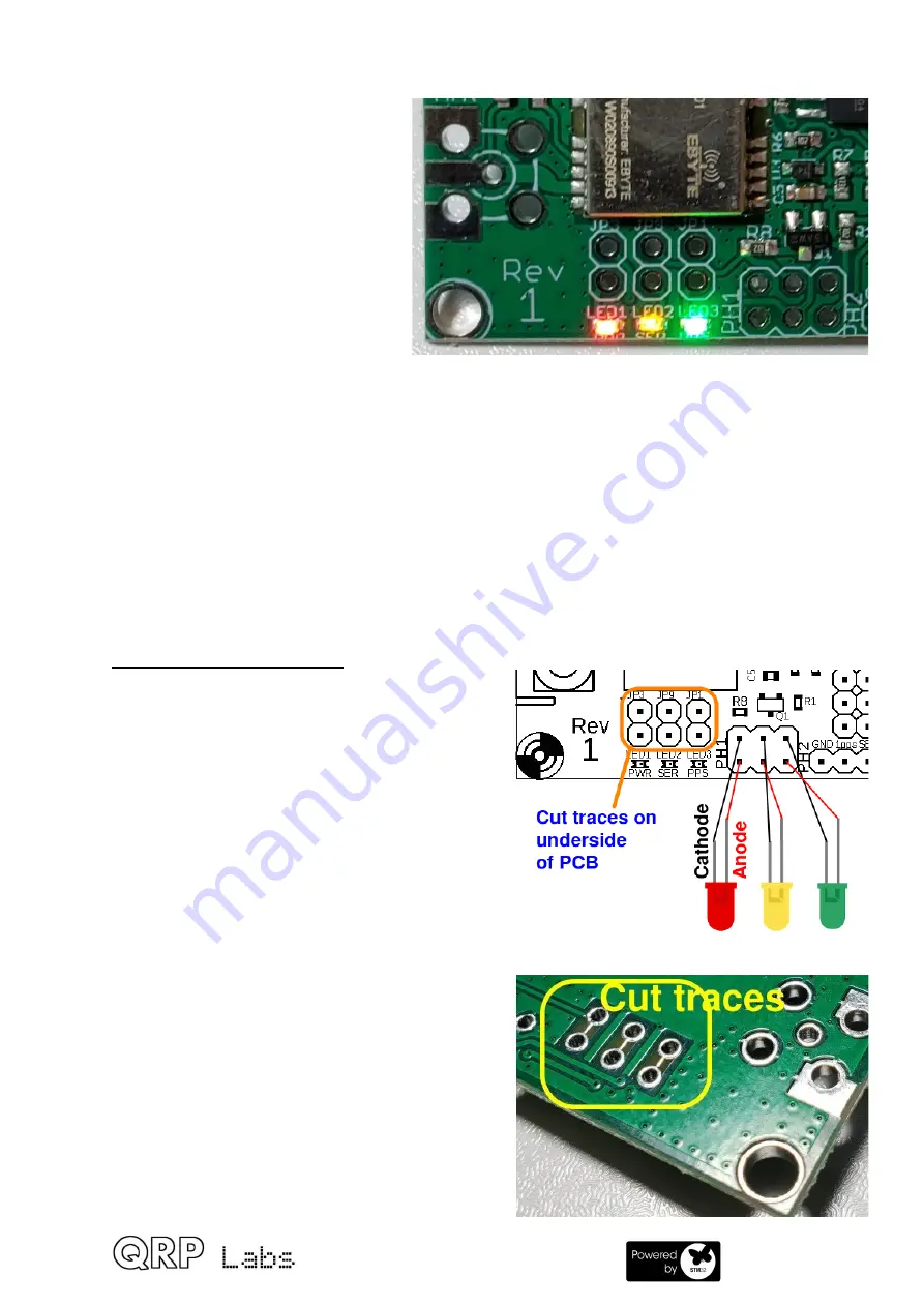
In this case, you can connect wires at pin header
PH1, as follows in the diagram (right). 

The cathodes (negative, indicated by black lines)
of the LEDs are connected to the pads nearer
the center of the board; the anodes (positive,
indicated by red lines) are connected to the pads
nearest the board edge. The sequence of the
pads, is as three pairs from left to right, as
Power (RED), Serial data (YELLOW) and 1pps
(GREEN) – in other words, the same order as
that of the SMD LEDs on the board. 

You would also need to cut the thin exposed
tinned copper traces on the underside of the
PCB, in order to disconnect the onboard LEDs.
This should be done with a sharp knife, carefully
so as not to damage any other nearby traces. 

QLG2 manual for firmware 1.00a

11

Summary of Contents for QLG2

Page 1: ...B to Serial converter 7 3 5 Powering the board from the USB port 10 3 6 Status LEDs 11 3 7 Fitting an ultracap a k a supercap 12 3 8 6 pin interface header 13 3 9 Jumper wire configuration 14 3 10 Int...

Page 2: ...for status indication Red Power Yellow Serial data and Green PPS 2 8 to 5V logic level conversion to provide 5V serial data for full compatibility with all QRP Labs kits Supports 2 8 3 3V logic OR 5V...

Page 3: ...Kit contents Know your QLG2 QLG2 manual for firmware 1 00a 3...

Page 4: ...cable It can be installed either facing to the right side of the board or facing the bottom side of the board Additionally there are pads for a micro USB connector if you should happen to prefer that...

Page 5: ...allation IMPORTANT The body of the SMA connector WILL DEFINITELY short to the center pad of the component footprint on the board This will not only short out the antenna rendering it completely ineffe...

Page 6: ...ports that access the USB to Serial converter On the 6 pin connector the pin labeled SER on the PCB silkscreen and GPS_TXD on the schematic is actually connected to the pin labeled TXD on the 4 pin h...

Page 7: ...e USB Virtual COM port to connect to this is different depending on whether you are using Windows or Linux 1 On Linux the QLG2 will appear as dev ttyACM0 or perhaps ACM1 ACM2 etc if you already have s...

Page 8: ...while out waiting for the next character Note that normal CAT host programs do not have this issue they send commands as a rapid burst of characters There are two possible ways around this 1 Type the...

Page 9: ...NSS module by the QLG2 USB to Serial converter A common error is to not calculate the checksum properly these are the last two characters of the command string The actual command is prefixed by a and...

Page 10: ...e tight flat against the board surface If you already feel now that it will not necessarily be a permanent connection then fit a 2 way pin header and use a header jumper as pictured right Now you migh...

Page 11: ...te diagnosis of correct operation of the QLG2 Connecting external LEDs You may wish to use external LEDs instead of the onboard ones For example you may wish to make the LEDs visible on the front pane...

Page 12: ...rt satellite fix computation within a second or two of power up Most amateur radio applications will not need this but the pads are made available on the board in case you do wish to use it Be careful...

Page 13: ...e of the board TXD Serial port transmit signal anything sent from the USB Terminal Emulator for example is delivered to this transmit output pin By default the baud rate is 9600 baud and the voltage l...

Page 14: ...bed in the former section headed Connecting external LEDs The jumpers fall into four categories 1 Onboard LED enable discussed above in section headed Connecting external LEDs 2 Power from USB discuss...

Page 15: ...LOWER 2 8V logic level 3 TXD voltage level the USB to Serial converter transmit output pin UPPER 2 8V logic level LOWER 5V logic level DEFAULT 4 RXD source where the USB to Serial converter receive s...

Page 16: ...connection no tinned copper traces on the underside of the board The nomenclature PA4 PA0 etc is a reference to the port pins of the microcontroller PA7 PA6 and PA5 are currently unused The operation...

Page 17: ...dule such as used in the Ultimate3S VFO Clock QCX and QCX kits blue colour or the QCX mini yellow green colour can be used here these types of LCD are available from many vendors If it is HD44780 comp...

Page 18: ...ory of the microcontroller chip for example 1_00 QG2 the QG2 extension is for QLG2 but because it is a FAT16 file system file names are limited to ye olde 8 3 format Thereafter a display is shown such...

Page 19: ...to noise ratio of the satellites being tracked higher numbers indicate stronger signal strength 3 13 QLG2 Commands QLG2 normally converts all incoming serial data from the USB host converts it to sta...

Page 20: ...d Works on any PC Operating System and in the same way Windows Linux Mac Secure firmware files are published on the QRP Labs website and are encrypted using 256 bit AES encryption technology Entering...

Page 21: ...firmware program file in the QLG2 microcontroller You may read the file from the QLG2 or write a new one just by dragging files in your file manager application On entering the Firmware update proced...

Page 22: ...drag it into the folder where the existing firmware file version is shown Or copy and paste it however you wish As soon as you copy the new file to the QLG2 QFU flash drive the QLG2 QFU bootloader era...

Page 23: ...5 Circuit diagram schematic and description QLG2 manual for firmware 1 00a 23...

Page 24: ...C6 0 1uF Capacitor 0603 D1 D2 D3 1N4148 Diode SOD 323 IC1 74ACT08 IC SOIC 14 IC2 MIC5219 3 3 IC SOT23 5 IC3 STM32F070F6P6 IC TSSOP 20 L1 L2 1uH Inductor 2012 LED1 Red LED 0603 LED2 Yellow LED 0603 LED...

Page 25: ...TTL voltage threshold compatibility and this means a 1 logic high is 2 4V so it is ideally suited for accurately converting GNSS module 2 8V logic to 5V levels Q1 implements a simple timer which caus...

Page 26: ...go pins installed on a special PCB Four 3mm screws in each corner of the boards ensure accurate alignment and the PCB under test is secured in place and under slight pressure to press the pogo pins us...

Page 27: ...connecting a Terminal Emulator via USB and observing the NMEA serial data These tests give a very high confidence that all QLG2 modules shipped by QRP Labs will be in proper working order 7 Acknowled...

Reviews: