


18
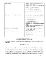
No RF Output
1. Improper connections between transceiver,
amplifier, and antenna
2. Transceiver and amplifier are set to different
bands
3. Improper Tuned Input adjustment
4. Defective RF I/O Switching PCB-350
5. Defective RF Output T/R Relay RY1
6. Defective Band Switch SW3A, SW3B
7. Defective Tuned Input Band Switch SW3C
Tuned Input can not be adjusted for proper
match
1. Defective Component Tuned Input PCB-450
2. Defective Tuned Input Band Switch SW3C
3. Components on LV & Bias PCB-260
a. Fuse F302
b. Bridge Rectifier D311
c. Capacitors C303 - C305
d. +12v Regulator Q303
4. Asso12v Supply wiring
5. Transceiver and amplifier are set to different
bands
6. Improper connections between transceiver,
amplifier, and antenna
Red Power LED not functioning
1. +12 VDC supply located on LV & Bias PCB-
260 and related wiring
2. LED D1 defective
Green Transmit LED not
1. +12 VDC supply located on LV & Bias PCB-
260 and related wiring
2. LED D2 defective
3. Relay K301 and related keying circuitry
CIRCUIT DESCRIPTIONS
Refer to the Appropriate Schematic Diagrams and PCB Layouts while you read the following
paragraphs.
POWER SUPPLY
Power transformer T1 supplies the power required to operate the Linear Amplifier. A dual-winding
primary allows the amplifier to be operated from120 VAC or 240VAC. These winding are
connected in parallel for 120 VAC operation or in series for 240 VAC operation. Two 10 ampere
or two 20 ampere fuses protect the transformer against overload depending on the primary
voltage. Capacitors C11 & C12 provide AC line bypassing.This amplifier uses a special
combination safety interlock/step-start circuit. Interlock switch SW1, On/OFF power switch
SW2A&B must be closed before power is supplied to the primary of transformer T1. Relay K-1


