


17
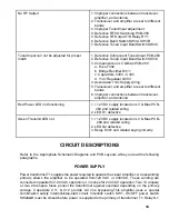
No Plate Idling current cut-off when amplifier is
not keyed or is in standby mode
1. Components on LV & Bias PCB-260
a. Transistor Q302
b. Diodes D303 - D310, D311
c. Resistor R301 &R304
d. Transient Voltage Suppressor TSD301
e. Capacitor C302
f. Resistors R307 - R310
g. Relay K301A
h. Zener Diode ZD301
2. Components on HV Diode PCB-110
a. Resistors R301 - R304
Meter Lamps do not light
1. Components on LV & Bias PCB-260
a. Fuse F302
b. Bridge Rectifier D311
c. Capacitors C303 - C305
d. +12v Regulator Q303
2. Asso12v Supply wiring
3. Meter Lamps PL1 - PL4 Meter Switch PCB-
510
No Grid Current Meter Indication with Plate
Current Indication OK
1. Components on LV & Bias PCB-260
a. Resistor R311
b. Capacitor C306
2. Grid Meter M-1
Amplifier will not key when transceiver is keyed
to transmit
1. Components on LV & Bias PCB-260
a. Fuse F301
b. Bridge Rectifier D302
c. Capacitor C301
2. Components on RF I/O Switching PCB-350
3. Operate Standby SW4 Front Panel
Amplifier will not key when transceiver is keyed
to transmit
1. Components on LV & Bias PCB-260
a. Fuse F301
b. Bridge Rectifier D302
c. Capacitor C301
2. Components on RF I/O Switching PCB-350
3. Operate/Standby SW4 Front Panel
ALC Inoperative
1. Improper connection between transceiver
and amplifier
2. POT R13 (ALC Adjust) on front panel


