background image


Contents 


Warnings ........................................................................................................................ 1 

Parts Identification ......................................................................................................... 2 

Control Panel ................................................................................................................. 3 

Remote Control .............................................................................................................. 4 

Portable Visualizer ......................................................................................................... 5 

Recommended Working Environment ........................................................................... 6 

Insert and Remove Micro SD Card (not supplied) ........................................................ 7 

USB Flash Drive (not supplied) ..................................................................................... 7 

Connect Portable Visualizer to external equipment ....................................................... 8 

Basic Operation ............................................................................................................ 13 

Advanced Functions..................................................................................................... 15 

Use the device as a camera .......................................................................................... 17 

Storage ......................................................................................................................... 18 

Problems and Solutions................................................................................................ 19 

Specifications ............................................................................................................... 20 


All manuals and user guides at all-guides.com

Summary of Contents for QPC80H2

Page 1: ...QPC80H2 Portable Visualizer Quick Guide This document is subject to change without notice All manuals and user guides at all guides com a l l g u i d e s c o m...

Page 2: ...Environment 6 Insert and Remove Micro SD Card not supplied 7 USB Flash Drive not supplied 7 Connect Portable Visualizer to external equipment 8 Basic Operation 13 Advanced Functions 15 Use the device...

Page 3: ...ing damaged When allocating the device please hold the base with both hands Do not carry the device by the gooseneck flexible tube or camera head with one hand Please prevent the camera head to hit th...

Page 4: ...ection Microphone Signal Indicator Control Panel Power Indicator Audio OUT DC 12V Power Socket VGA OUT Micro SD Card Slot Camera Head HDMI OUT LED Lamp Light VIDEO OUT USB A for flash drive USB mouse...

Page 5: ...still works Mirror the current image Capture and save the current image Up Down Increase Decrease brightness Record video Left Right Zoom out Zoom in Enter Exit Playback Mode Auto focus or confirm Ro...

Page 6: ...o show or hide OSD menu Freeze Freeze Unfreeze the current image Snap Capture and save the current image Mirror Mirror the current image Record Record video Rotate Rotate Playback Enter Exit playback...

Page 7: ...d and adjust it to the position where you want to shoot the image Gooseneck Bend the gooseneck flexible tube gently by hand and place the camera head to the preferable height and orientation Support S...

Page 8: ...nt according to the recommendation described above please use the rotation key of the control panel or the remote control to adjust the orientation Suggested minimum height from device in telescope mo...

Page 9: ...apture image will save to SD card instead of internal memory 3 Push SD card lightly with your finger the SD card can be removed USB Flash Drive not supplied When USB flash drive plugs in USB Type A su...

Page 10: ...the power cord Plug in the power adapter to the device DC 12V IN power socket first and then connect the AC power cord to a 100V 240V AC power source Note The plug type of AC cord varies depending on...

Page 11: ...N HDMI OUT VGA VGA OUT VGA IN VIDEO VIDEO OUT VIDEO IN AUDIO AUDIO OUT AUDIO IN USB TYPE B Port TYPE A Port TYPE A Port TYPE B Port RS232 control protocol RS232 Setting Baudrate 9600 bps Parity check...

Page 12: ...8 0x02 0X14 0x17 0x54 SPLIT 0x48 0x02 0X14 0x18 0x54 ROTATE 0x48 0x02 0X14 0x19 0x54 XGA 0x48 0x02 0X14 0x1A 0x54 B W 0x48 0x02 0X14 0x1B 0x54 TITLE 0x48 0x02 0X14 0x1C 0x54 TEXT 0x48 0x02 0X14 0x1D 0...

Page 13: ...to the table below to select the image output you prefer Output Image ratio TV System Resolution HDMI 16 9 1280x720 1280x800 1920x1080 16 10 1280x800 1920x1200 4 3 1024x768 1280x1024 VGA 16 9 1280x720...

Page 14: ...GA cable to connect the VGA OUT port of the device with the VGA input port of TV or projector Note Use Source Button to switch between modes Using USB connection Press Menu System Setting USB to PC PC...

Page 15: ...20 1200 Focus Mode Auto Focus Manual Focus Mask Activate the Mask function Highlight Line Activate the highlight line function MIC ON OFF Image Setting Photo Resolution 1280 720 1920 1080 2688 1522 Re...

Page 16: ...de Up down Mode Effect Normal Black white Mode Negative Mode Flicker 50HZ 60HZ Brightness Sharpness DNR Contrast Saturation Use to adjust its setting Delay Time lapse Photography ON OFF ON OF Interval...

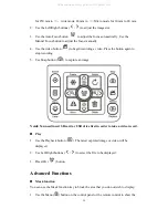
Page 17: ...ding 5 Use Snap button to capture an image Note You need insert SD card or USB drive first in order to take a video record Play 1 Use the Playback button The latest captured image or video will be dis...

Page 18: ...panel or the remote control to show the menu 2 Use the arrow buttons to make your selection Menu Delay Photography Transfer the captured image to computer Please note all recorded videos are in AVI f...

Page 19: ...xample Skype Connecting the microscope To connect the device with a microscope can display microscopic objects on a large screen 1 Adjust the microscope and the objects to be focused 2 Please select a...

Page 20: ...ower of the device 2 Please unplug and remove the power cord and all other cables from the device 3 Please refer to the diagram to the right to fold the gooseneck flexible tube for storage All manuals...

Page 21: ...witched to the correct source of signals Switch to the correct source of signals The computer transfer key VGA is activated Press the source of signal CAM HDMI is activated Press the source of signal...

Page 22: ...P 1280 720 1080P 1920 1080 1280 800 1920 1200 Total Pixels 5 0 Mega Frame Rate 1080p 30fps Input Connector HDMI 1 4 Compliant 1 VGA DB15FLC 1 Output Connector VGA DB15FLC 1 C Video RCA 1 HDMI 1 RS232...

Reviews: