Chapter 1 Introduction to the Web Smart PoE Switch
1.3 LEDs Definition
This device provides extensive LEDs to show the activities on power, system and ports.
See the following description for your reference:
LED
Status
Operation
PWR/SYS
Steady Green
Power on.
Blinking Green System booting up.
Off
Power off or fail.
PoE/Max
Steady Green
Over PoE max power budget (50W)
Off
No over PoE max power budget (50W)
LINK/ACT
Steady Green
1000Mbps connected.
Steady Amber
10/100Mbps connected
Blinking
Sending or receiving data.
Off
Port disconnected or link fail.
PoE
Steady Green
PoE power output on.
Off
PoE power output off.
The Reset Button
Reset the switch to its factory default configuration via the RESET button. Press the RESET button
for ten
seconds and release. The switch automatically reboots and reloads its factory configuration
file. The RESET button is on the front panel of the switch.
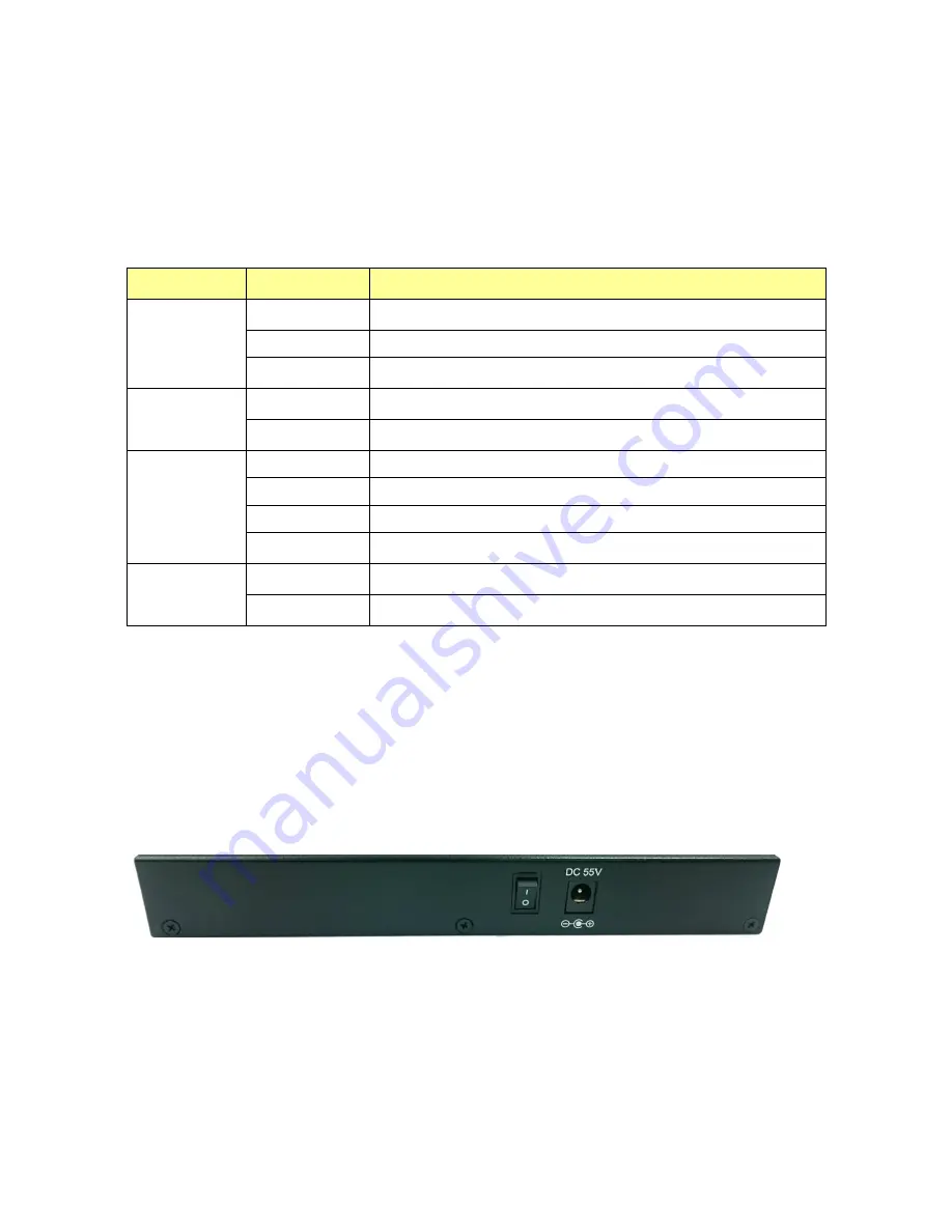
1.4 The Rear Panel
The following figure shows the rear panel of the switch:
Power Receptacle
To be compatible with the electric service standards around the world, the switch is designed to
afford the power supply in the range from 100 to 240 VAC, 50/60 Hz. Please make sure that your
outlet standard to be within this range.
To power on the switch, please plug the female end of the power cord firmly into the receptacle of
the switch, the other end into an electric service outlet, and use the
POWER ON/OFF
switch to
have the Switch power on or off. After the switch powered on, please check if the PWR/SYS LED is
lit for a normal power status.
Summary of Contents for QMP1005G
Page 1: ...5 Port Gigabit Management PoE switch User Manual...
Page 2: ...Default IP 192 168 2 1 Username Password admin...
Page 14: ...3 4 2 Port Based VLAN Click Add VLAN and it will show as below Select the VLAN member port...
Page 23: ...3 12 Password In Password page you can change user name and password for security...


