QED WELL WIZARD Installation Manual Download Page 23

Well Wizard®


Installation and Operation Manual


Rev. E   06-05-2023 


21 


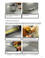
9.  Connect the tubing onto the fitting on the drop tube weight, following the same procedures as in 

#6 above for either compression or barb fittings. 

10.  Insert the drop tube weight assembly into the well and begin lowering the tubing.  Be sure to 

control the rate of descent – do not let the tubing free fall into the well. Lower the weight until just a 
few feet of tubing remains out of the well. 

11.  Connect the top end of the drop tubing to the fitting on the pump inlet, following the same 

procedures as in #6 above for either compression or barb fittings. 

12.  Carefully raise the pump for installation into the well. Be sure to allow enough tubing slack to 

prevent the tubing from kinking, but don’t allow it to touch the ground. 

13.  Begin lowering the pump into the well by spooling off the twin-bonded tubing and support cable. 

Have the support cable positioned so it can easily feed into the well without tangling or kinking. 

14.  When the pump is lowered to the point where only a few feet of tubing and cable remain, hold or 

clamp the tubing to prevent it from slipping and install the well cap. 

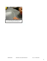
15.  Separate about 8-12” (20-30 cm) of the twin-bonded tubing. Push the discharge tubing through 

the compression fitting on the cap to the appropriate height based on the cap design. Refer to the 
separate instruction sheet included with the well cap. 

16.  Cut the air supply tubing to the proper length to fit either over the air connection barb fitting or 

inside the air connection compression fitting (varies with well cap model). 

  If a barb connection, slide the pinch clamp over the air tubing first, and then push the tubing 

fully onto the barb. Slide the clamp into place over the barb and tighten it with the clamp tool. 

  If the air supply on the cap uses a compression fitting connection, push the air tubing fully into 

the fitting, and then tighten the nut to compress the brass ferrule and retain the tubing. 

17.  QED recommends testing for proper operation of the pump before moving on to the next well. 

Summary of Contents for WELL WIZARD

Page 1: ...Well Wizard Installation and Operation Manual Rev E 06 05 2023 Dedicated Monitoring Systems INSTALLATION GUIDEE P N 34999 QEDENV COM...

Page 2: ...ing Your Well Wizard System 11 12 Installing the Bladder Pump Inlet Screen 13 Installing or Replacing Pump Fittings and Connectors 14 Attaching and Re attaching Pump Fittings and Connectors 15 16 Inst...

Page 3: ...h well The pump controller compressed air or gas source and water quality monitoring components are portable and are transported from well to well This document is intended to assist you with the prop...

Page 4: ...Well Wizard Installation and Operation Manual Rev E 06 05 2023 2 Sampling System Type A Figure A 1 shows the Type A sampling system the basic bladder pump...

Page 5: ...Well Wizard Installation and Operation Manual Rev E 06 05 2023 3 Sampling System Type L Figure A 2 shows the Type L sampling system a bladder pump with a drop tube inlet extension...

Page 6: ...r components of the pump without tools by unscrewing the inlet and discharge assemblies by turning them counter clockwise and pushing the bladder cartridge out of the pump body The bladder cartridge c...

Page 7: ...r gas delivered to the pump through the air supply tubing When the pressurized air fills the chamber between the pump body and the bladder it squeezes the bladder closing the bottom check valve and li...

Page 8: ...r pressure within the pump falls below the hydrostatic pressure the bottom check valve opens and allows water to enter the pump filling the inside of the bladder Caution A Well Wizard pump bladder can...

Page 9: ...contacting the bladder and ensure proper performance by keeping larger sand particles out of the check valves The use of an inlet screen extends the pump warranty to ten years Well Cap The pump and tu...

Page 10: ...Well Wizard Installation and Operation Manual Rev E 06 05 2023 8 Well Cap Types Recessed Well Cap Locking and Sealing Well Cap...

Page 11: ...Well Wizard Installation and Operation Manual Rev E 06 05 2023 9 Standard Pressure 150 psi Max P N 34132 High Pressure 300 PSI Max P N 34642 Ultra High Pressure 500 PSI Max P N 34506...

Page 12: ...driven Model MP40C portable oilless compressors for use with the MicroPurge controllers Where compressed gas cylinders are preferred QED can supply either nitrogen or CO2 pressure regulators with qui...

Page 13: ...et screen or connection of the drop inlet tubing where used 7 Make sure you have the necessary tools and supplies before you begin The installation instructions included with some components should id...

Page 14: ...e desired submergence In general pumps should have at least 10 feet of submergence and systems using drop tube inlets should have 25 feet of submergence over the pump Call QED if you have any question...

Page 15: ...1 Open the plastic wrapping and remove the screen 2 Holding the pump inlet housing with an open end or adjustable wrench thread the screen into the female thread in the inlet housing NOTE Failure to h...

Page 16: ...el Stainless Steel Compression Fittings Stainless steel compression fittings which include four pieces come to you completely assembled finger tight Note Be careful not to fully disassemble compressio...

Page 17: ...d separately and not previously assembled Fully insert the tubing into the fitting until it bottoms out on the shoulder inside the fitting The length of tubing inserted into the fitting should be 0 80...

Page 18: ...ollow these steps Cut the tubing cleanly and squarely to length Push the tubing into the completely assembled connector until it contacts the shoulder inside the fitting see figure 7 Tighten the nut w...

Page 19: ...stallation If your Well Wizard system was ordered with pre cut tubing but the tubing has not been pre assembled with the pumps by request skip down to the instruction below under Installing Pump Syste...

Page 20: ...0 1300 and 1500 Series models 1 Separate the ends of the twin bonded tubing about 8 12 inches 20 30 cm 2 For pumps that have staggered height air and discharge fittings shorten the length of the disch...

Page 21: ...g to the Well Cap To attach the well cap separate about 8 12 20 30 cm of the twin bonded tubing Push the discharge tubing through the compression fitting on the cap to the appropriate height based on...

Page 22: ...to the support bracket located on the top of the pump using the U shaped stainless steel shackle Tighten the shackle pin with needle nose pliers Strip about 6 of the support cable outer coating from...

Page 23: ...t can easily feed into the well without tangling or kinking 14 When the pump is lowered to the point where only a few feet of tubing and cable remain hold or clamp the tubing to prevent it from slippi...

Page 24: ...ated on the top of the pump using the U shaped stainless steel shackle Tighten the shackle pin with needle nose pliers Strip about 6 of the support cable outer coating from the other end of the cable...

Page 25: ...ing knives blades or other sharp tools 1 Measure back 6 from the end of the cable 2 At the 6 mark cut in a circular direction to score through the polyethylene coating 3 At the circular cut flay the t...

Page 26: ...Well Wizard Installation and Operation Manual Rev E 06 05 2023 24 5 You will now be able to grab the edge at the circular cut and peel the coating off...

Page 27: ...ld show 30 seconds Refill and 30 seconds Discharge cycle times 3 Start the compressor Before cycling the pump set the pump pressure regulator on the controller to approximately 50 of the pump depth in...

Page 28: ...ycle button on the lower left corner of the keypad press until the pump is in the discharge cycle as indicated on the LCD display by an arrow 2 Allow the bladder to fully discharge then observe the pr...

Page 29: ...the bottom of the well when installed If the well depth measurement matches the well data sheet and the total length of the tubings pump and drop tube weight match the desired intake point then tubing...

Page 30: ...foot of pump depth Higher pressures than this can cause the bladder to be squeezed too tightly during discharge a condition which can prevent the bladder from expanding during refill To avoid this co...

Page 31: ...Well Wizard Installation and Operation Manual Rev E 06 05 2023 29 Sampling Pump Troubleshooting Guide...

Page 32: ...s that carry shelf lives i e calibration solutions Also the warranty does not cover products damaged by improper installation or application misuse abuse neglect or accident NOTE THE FLOW CELL SYSTEMS...

Page 33: ...essories equipment or materials not supplied by QED QED shall be released from all obligations under all warranties if any Product covered hereby is repaired or modified by persons other than QED s se...

Reviews: