


Network Switch Installation Guide
21
QuantaMesh T7000 Series
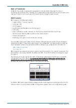
QuantaMesh T7032-IX1 supports 32 QSFP28 (10/40 or 25/50/100GbE speed) ports and
QuantaMesh T7032-IX1B supports 32 QSFP28 (10/40 or 25/50/100GbE speed) ports and is
equipped with BMC in a compact rack unit size. By leveraging merchant silicon chipsets, the
T7032-IX1 and T7032-IX1B provides a high performance, high-density Ethernet switch at an
affordable price. With ONIE (Open Network Installation Environment) pre-loaded, the T7032-
IX1 and T7032-IX1B can be used with multiple operating system that support ONIE installers to
achieve agile installation and fast response as demands change.
Chassis for the T7032-IX1/IX1B Switch
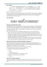
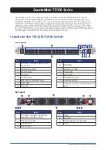
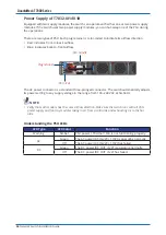
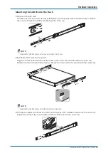
Front panel
PSU 1
PSU 2
T7032-IX1
QuentaMesh
1/33
2/37
34/161
38/163
35
39
36/162
40/164
1
2
7/57
8/61
58/173
62/175
59
63
60/174
64/176
7
8
5/49
6/53
50/169
54/171
51
55
52/170
56/172
5
6
3/41
4/45
42/165
46/167
43
47
44/166
48/168
3
4
9/65
10/69
66/177
70/179
67
71
68/178
72/180
9
10
15/89
16/93
90/189
94/191
91
95
92/190
96/192
15
16
13/81
14/85
82/185
86/187
83
87
84/186
88/188
13
14
11/73
12/77
74/181
78/183
75
79
76/182
80/184
11
12
17/97
18/101
98/193
102/195
99
103
100/194
104/196
17
18
23/121
24/125
122/205
126/207
123
127
124/206
128/208
23
24
21/113
22/117
114/201
118/203
115
119
116/202
120/204
21
22
19/105
20/109
106/197
110/199
107
111
108/198
112/200
19
20
25/129
26/133
130/209
134/211
131
135
132/210
136/212
25
26
31/153
32/157
154/221
158/223
155
159
156/222
160/224
31
32
29/145
30/149
146/217
150/219
147
151
148/218
152/220
29
30
27/137
28/141
138/213
142/215
139
143
140/214
144/216
27
28
2
3
13
12
14 15
5
4
1
7
6
8 9 10 11
No.
Item
No.
Item
1
AC Power Connector (PSU1) with
dust cover
9
PSU2 LED
2
QSFP28 Port LEDs
10
System info. LED
3
QSFP28 Ports
11
Power LED
4
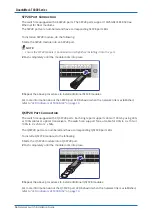
USB Port
12
Speed LED
5
Console Port
13
Management Port
6
BMC LED (T7032-IX1B only)
14
Link/Activity LED
7
PSU1 LED
15
AC Power Connector (PSU2) with dust
cover
8
Fan LED
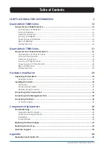
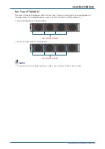
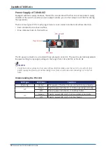
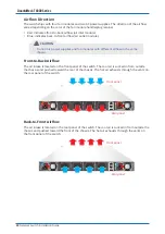
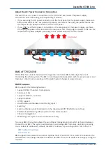
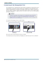
Rear panel
PSU2
PSU1
AC
DC
FAN4
FAN3
FAN2
AC
DC
FAN1
1
5
7
6
4
3
2
3
2
1
8
4
No.
Item
No.
Item
1
AC Power Connector (with Plug
Retainer and Power Cord)
5
PSU2
6
Fan LEDs
2
PSU Warning LED
7
Hot-swappable Fan Modules
3
PSU DC LED
8
PSU1
4
PSU AC LED


