background image

BMC

D

ASHBOARD

 4-15

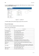
To open the 

Dashboard

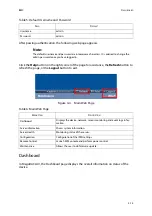
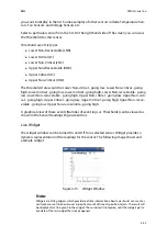
 page, click Dashboard from the main menu. A sample screenshot 

of the Dashboard page is as follows:

Figure 4-5.

Dashboard

A brief description of the Dashboard page is given in the next section.

Device Information

The Device Information displays the following information:

Table 7: Device Information Page

I

TEM

D

ESCRIPTION

Firmware Revision

The revision number of the firmware.

Firmware Build Time

Firmware date and time.

BIOS Version

The current BIOS firmware version.

PDB Firmware Version

The current PDB firmware version.

PSU0 MFR Revision

Display PSU0 manufacture revision.

PSU0 Firmware version

Display PSU0 Firmware version.

PSU1 MFR Revision

Display PSU1 manufacture revision.

PSU1 Firmware version

Display PSU1 firmware version.

Top PSU Max output Power

Display Top power supply max output power (Watts).

Bottom PSU Max output Power

Display Bottom power supply max output power (Watts).

MB Position

Display the current position of the mainboard within the chassis.

BMC NIC

Display current used NIC.

System MAC

The maximum MAC address of system LAN port is 8. From Grant-key 
platform, BMC support to show LAN Card Type (LOM/OCP Mezzanine/
Quanta Mezzanine) for System MAC.

BMC Date & Time

The current time of BMC system.

BMC Chipset

This field shows BMC chipset type.

Summary of Contents for QuantaGrid D51PH-1ULH

Page 1: ...Version 1 0 QuantaGrid Series D51PH 1ULH Hybrid Scale Out High Computing Storage Server Service Guide...

Page 2: ...D 1 11 LAN Port LED 1 11 BMC Management Port LED 1 12 Installing Hardware Safety Measures 2 1 Power Supply Unit 2 2 Removing the Redundant Power Supply Unit 2 2 Installing the Power Supply Unit 2 3 HD...

Page 3: ...ink 2 19 Installing a Processor Heat Sink 2 19 Processor 2 21 Removing the Processor 2 21 Installing the Processor 2 22 Expansion Card 2 24 Removing a Riser Assembly 2 24 Installing a Riser Assembly 2...

Page 4: ...g Utility 3 16 BIOS Revision 3 16 Clear CMOS 3 16 Clear Password 3 16 BIOS Update Via BMC Instructions Optional 3 17 Server Management 3 18 Console Redirection 3 18 Serial Configuration Settings 3 18...

Page 5: ...overy Utility 4 4 WebUI Update 4 4 BMC Recovery 4 5 Recovery Process in DOS System 4 5 Recovery Process in Linux System 4 5 Recovery Process in Windows System 4 5 SMASH 4 6 System Level Commands 4 7 B...

Page 6: ...Mode 4 34 Network 4 35 PEF 4 38 RADIUS 4 46 Remote Session 4 47 SMTP 4 48 SOL 4 51 SSL 4 51 User Management 4 55 Virtual Media 4 59 SNMP 4 60 UTC Timezone 4 60 LAN Port Settings 4 61 Remote Control 4...

Page 7: ...VI Connectors Connectors 5 1 Mainboard 5 1 Connectors 5 1 Regulatory and Compliance Information...

Page 8: ...owners Version 1 0 May 12 2015 Disclaimer The information in this document is subject to change without notice The manu facturer makes no representations or warranties with respect to the contents her...

Page 9: ...m Intended Application Uses This product was evaluated as Information Technology Equipment ITE which may be installed in offices schools computer rooms and similar commercial type loca tions The suita...

Page 10: ...and the names of the folders menus programs and files Enter type face denotes keyboard keys WARNING Warning information appears before the text it references and should not be ignored as the content...

Page 11: ...ides information regarding the BIOS architecture BIOS update utility server management checkpoints and error handling found in the sys tem Chapter 4 BMC This section provides information and key featu...

Page 12: ...About the System Chapter 1 This section introduces the system its different configuration s and the main features...

Page 13: ...eases the efficiency because of its built on board design All key functions are built on the motherboard including two 1GbE RJ45 ports for accessing or managing the server from multiple networks one d...

Page 14: ...DIMM Memory size 32 GB 16 GB 8 GB RDIMM 64 GB 32 GB LRDIMM Storage controller Onboard Intel C610 10x SATA 6Gb s ports SATA RAID 0 1 10 Optional controller Quanta LSI 2208 6Gb s SAS mezzanine Quanta LS...

Page 15: ...to ordering info or CCL Rating per PSU inlet 100 240Vac 10 5A 50 60Hz Fan 6x systems fans System management IPMI v2 0 Compliant on board KVM over IP support Operating environment Operating temperatur...

Page 16: ...ENTS 1 4 1 2 Package Contents 1 the system 1 processor heat sink 1 power supply unit 1 power cord optional 1 utility CD This Guide included 1 rail kit Note Note For exact shipping contents contact you...

Page 17: ...ABOUT THE SYSTEM A TOUR OF THE SYSTEM 1 5 1 3 A Tour of the System System Overview Figure 1 1 System Component Overview 1 2 3 8 4 5 6 9 7 10 11 12 13...

Page 18: ...y unit supports Quanta LSI 2208 SAS mezzanine 7 Quanta mezzanine slot Supports Quanta LAN SAS mezzanine only 8 Power Supply Unit Redundant Power Supply Unit PSU 700W high efficiency redundant PSU 240V...

Page 19: ...ay 3 HDD tray handle Hold to pull out the HDD tray from the chassis or push the HDD tray into the chassis Table 1 4 Front Control Panel View NO NAME DESCRIPTION 1 Power Button with LED Power Button Pu...

Page 20: ...D Amber Off Normal On DC off and critical error Blinking DC on and critical error 6 LAN 1 LED Blue On link Blinking LAN access 7 LAN 2 LED Blue On link Blinking LAN access 8 HDD Array LED Amber Off HD...

Page 21: ...2 Expansion slot Supports Quanta mezzanine PCIe Gen3 x16 3 System Rear I O Mainboard MB I O features Table 1 6 Rear Panel View NO NAME DESCRIPTION 1 Management port Connects for remote management 2 V...

Page 22: ...the power cord 4 Handle Hold to remove the PSU from the chassis bay 5 PSU LED Power LED Green On Output on and OK Blinking AC present Status LED Amber On AC core unplugged or AC power lost with a seco...

Page 23: ...mainboard has two i350 Ethernet controller Each RJ45 connector has two built in LEDs See the following illustration and table for details Figure 1 7 RJ45 LAN Connector COLOR STATUS Blue On Continuous...

Page 24: ...gement Port LED Table 1 10 Management Port LED Behavior STATUS SPEED LED LINK ACTIVITY LED Unplug Off Off Plug in no access Off Green on 1G Link Active Amber on Green blinking 100M Link Active Green o...

Page 25: ...Installing Hardware Chapter 2 This section provides guidance information to properly service components in the sys tem...

Page 26: ...ected to a power supply can be extremely dangerous Follow the guidelines below to avoid personal injury or damage to the server WARNING Always disconnect the server from the power outlet whenever you...

Page 27: ...page 1 10 Removing the Redundant Power Supply Unit 1 Locate the redundant power supply to service 2 Release power cord from the power cord clamp 3 Unplug the AC power cord from the power supply 4 Pres...

Page 28: ...let connector on the left side and slide the new power supply mod ule into the power supply bay and gently press it in place until it is flush with the chassis 5 The locking latch clicks when the powe...

Page 29: ...HDDs can be serviced without removing the system from the rack All other component servicing require the system to be removed from the rack and placed on a stable clean flat surface Releasing the HDD...

Page 30: ...thly until fully extend Figure 2 3 Releasing and pulling the HDD Tray out from the chassis Securing a HDD Tray 1 Using the tray handle gently push the tray into the chassis Figure 2 4 Pushing the HDD...

Page 31: ...g Hard Disk Drives replacement must be performed within 30 minutes without turning off system WARNING Repairs should be performed by a certified service technician Damage to the system or com ponents...

Page 32: ...rerequisite Check the HDD Array LED on the front control panel and pull out the HDD tray from the chassis See Releasing the HDD Tray on page 4 Locate the HDD carrier in the HDD array Figure 2 6 Check...

Page 33: ...ull the handle to open position as shown Figure 2 7 Removing a HDD carrier from the HDD tray 2 Remove the HDD carrier assembly from the HDD tray on the chassis 3 Remove screw s securing the HDD to the...

Page 34: ...h HDD to HDD tray Prerequisite Prerequisite Locate the HDD carrier slot on the chassis for servicing 1 Align the screw holes on the HDD carrier assembly bracket with the wells on the HDD Secure the ca...

Page 35: ...sembly with the carrier slot on the HDD tray on the chassis Place the HDD carrier on the HDD tray on the chassis Push the handle of HDD car rier assembly to close position to secure the HDD carrier as...

Page 36: ...cedure illustrates the system 1 Press the top cover release button A 2 Slide the top cover away from the HDDs B Figure 2 11 Removing the Top Cover Installing the Top Cover 1 Place the top cover on the...

Page 37: ...INSTALLING HARDWARE INSTALLING THE TOP COVER 2 12 2 Slide the cover toward the front of the chassis until it lock in place B Figure 2 12 Installing the Top Cover A B...

Page 38: ...rimary fan fails Figure 2 13 Fan Module Removing a Fan Module The system supports six fan modules 1 Pull the system out of the rack 2 Remove the top cover 3 Remove the air duct 4 Locate the fan module...

Page 39: ...7 Pull the fan module up to remove it Figure 2 14 Removing a Fan Module Installing a Fan Module 1 Locate the slot for the fan module 2 Align the fan module in the fan cage CAUTION POSITION THE FAN MOD...

Page 40: ...MODULE 2 15 3 Install the fan module and seat in the chassis Figure 2 15 Installing a Fan Module 4 Guide the cable through the corresponding opening 5 Replace the air duct 6 Replace the chassis top co...

Page 41: ...be occupied at all times by either a memory mod ule or dummy DIMM Table 1 DDR4 Registered Maximum Frequency Support per channel TYPE RANKS PER DIMM AND DATA WIDTH DIMM CAPACITY GB SPEED MT S VOLTAGE...

Page 42: ...ving a Memory Module 3 Lift out the memory module Installing a Memory Module 1 Remove the top cover See Removing the Top Cover on page 2 11 WARNING Memory modules remain hot after the system is powere...

Page 43: ...A MEMORY MODULE 2 18 Push the memory module firmly into the memory module slot The locking latches should automatically close over the edges of the memory board when fully inserted into the slot Figur...

Page 44: ...k 3 Remove the heat sink 4 Repeat steps for the other heat sink Installing a Processor Heat Sink 1 Remove the top cover 2 Align the heat sink over the processor plate Note All the instructions and ima...

Page 45: ...OR HEAT SINK 2 20 3 Install the heat sink Make sure the screw s are inserted into the screw wells Figure 2 19 Removing the Heat Sink 4 Tighten the screw s in the order shown 5 Repeat steps for the rem...

Page 46: ...re 2 20 Unlocking the locking lever 5 Push the release lever down and in to release the load plate Figure 2 21 Unlocking the locking lever Note All the instructions and images in this section are for...

Page 47: ...Installing the Processor 1 Push the locking lever down and in to unlock the load plate 2 Push the release lever down and out to release the load plate 3 Lift the load plate upright 4 If there is a pro...

Page 48: ...ing tab D on socket 9 Install the processor Figure 2 24 Installing the processor 10 Lower the processor load plate over the processor and secure the locking levers to lock the processor in place Figur...

Page 49: ...the installation of a mezzanine card follow these guide lines 1 Remove the system from the rack to power it down 2 Remove the top cover 3 Locate the riser assembly in the rear of the chassis 4 Pull t...

Page 50: ...Install the assembly on the chassis and press down firmly to connect it to the main board A 2 Twist the securing plug B and then release to secure the assembly in place Figure 2 27 Installing the Rise...

Page 51: ...power it down 2 Remove the top cover See Removing the Top Cover on page 2 11 3 Remove the screws securing the OCP assembly to the chassis 4 Remove the screws securing the OCP assembly to the standoff...

Page 52: ...OCP mezzanine board in an anti static bag 7 Replace the OCP mezzanine board 8 Install the top cover See Installing the Top Cover on page 2 11 9 Replace the system in the rack to power on Installing a...

Page 53: ...INSTALLING HARDWARE INSTALLING AN OCP MEZZANINE BOARD 2 28 3 Remove the filler from the bracket Figure 2 30 Removing the Bracket 4 Install the suitable bracket to chassis...

Page 54: ...INSTALLING AN OCP MEZZANINE BOARD INSTALLING HARDWARE 2 29 5 Align the OCP assembly to the standoffs and secure with screws Figure 2 31 Installing the Bracket...

Page 55: ...CP MEZZANINE BOARD 2 30 6 Secure the OCP assembly to the chassis with screws Figure 2 32 Installing the OCP Mezzanine Board 7 Install the top cover See Installing the Top Cover on page 2 11 8 Replace...

Page 56: ...INSTALLING AN OCP MEZZANINE BOARD INSTALLING HARDWARE 2 31...

Page 57: ...BIOS Chapter 3 This section provides information regarding the BIOS architecture BIOS update utility server management checkpoints and error handling found in the system...

Page 58: ...a of the screen and has dedicated functionality The following table lists and describes each functional area Entering BIOS Setup BIOS Setup is started by pressing DEL or F2 during boot time when the O...

Page 59: ...Esc key provides a mechanism for backing out of any field When the Esc key is pressed while editing any field or selecting features of a menu the parent menu is re entered When the Esc key is pressed...

Page 60: ...o appear If Yes is highlighted and Enter is pressed all Setup fields are set to their previous values If No is highlighted and Enter is pressed or if the Esc key is pressed the screen is returned to t...

Page 61: ...ument is to serve as a reference point The Comments column provides additional information where it may be helpful This information does not appear in the BIOS Setup screens Information in the screen...

Page 62: ...he BIOS Vendor Core Version Information only Displays the AMI BIOS Core version Compliancy Information only Displays the BIOS compliancy Project Version Information only Displays the Project version B...

Page 63: ...me ters SATA Configuration SATA Devices Configuration set Serial Port Console Redirec tion Serial Port Console Redirection Onboard Device Configura tion Onboard Device Parameters PCI Subsystem Setting...

Page 64: ...e 5 IntelRCSetup Screen Description SETUP ITEM OPTIONS HELP TEXT COMMENTS Pwr Perf Profiles Custom Energy Saving Balanced Virtualization High Performance Configure your own power and performance setti...

Page 65: ...ngs IIO Configura tion Displays and provides option to change the IIO Settings PCH Configura tion Displays and provides option to change the PCH Settings Server ME Con figuration Configure Server ME T...

Page 66: ...OS successfully loaded or follows the O S Boot Watch dog Timer policy OS Wtd Timer Timeout 5 minutes 10 minutes 15 minutes 20 minutes Configure the length of the OS Boot Watchdog Timer Not avail able...

Page 67: ...will auto boot into BIOS setup menu To access this screen from the Main screen select Boot Options Figure 3 5 Boot Options Screen Table 7 Boot Options Screen Description SETUP ITEM OPTIONS HELP TEXT C...

Page 68: ...order Default priority 1st USB 2nd Network 3rd Hard Disk 4th CD DVD 5th Other Hard Drive BBS Priorities Set the order of the legacy devices in this group Only appears when at least one device is detec...

Page 69: ...to the factory defaults or to save or restore a set of user defined default values If Restore Defaults is selected the default settings noted in bold in the tables in this chapter will be applied If R...

Page 70: ...nges Discard Changes Discards changes done so far to any of the setup options Restore Defaults Restore Load Default values for all the setup options Save as User Defaults Save the changes done so far...

Page 71: ...reset the system configuration is detected the BIOS loads the default system configuration values during the next POST The request to reset the system to the defaults can be sent in the following way...

Page 72: ...the rule and use official provided package to update BIOS under DOS Linux EFI shell environment Using incorrect flash option to flash BIOS may cause damage to your system This utility loads a fresh c...

Page 73: ...ear CMOS The following steps will load the BIOS defaults by jumper 1 Power down the system 2 Move CMOS clear jumper from pins 1 2 to pins 2 3 for a few seconds 3 Move CMOS clear jumper back to pins 1...

Page 74: ...ay be system couldn t complete POST or system stop somewhere with CPU exception unexpected hardware error In order to rebuild BIOS back functionality remote server manager could provide a safety healt...

Page 75: ...from both sources are considered valid and video is displayed to both outputs As an option the system can be operated without a host keyboard or monitor attached to the system and run entirely via th...

Page 76: ...ape sequence The escape sequence in the following table is an input sequence This means it is sent to the BIOS from the remote terminal Reset BIOS provides another friendly method to reset system from...

Page 77: ...cludes the necessary PXE ROMs in the BIOS image for the onboard controllers The legacy PXE ROM is required to boot a non EFI operating system over the network Checkpoints A checkpoint is either a byte...

Page 78: ...BIOS CHECKPOINTS 3 21 b Error code POST Error MRC Fatal Warning Code One reset switch To trigger system reset...

Page 79: ...BMC Chapter 4 This section provides information and key features of BMC Baseboard Management Controller...

Page 80: ...or remote management via network The FRU information report includes main board part number product name manu facturer etc Health status Hardware monitoring report Events log view and clear Event noti...

Page 81: ...AST2400 is assigned to its Shared NIC LAN and a dedicated NIC Default in the system IPMI Specification v2 0 defines how IPMI messages encapsulated in RMCP RMCP packet format can be sent to and from t...

Page 82: ...s not have a local RTC to know what time it is Each time BMC will get the current time from system PCH after BMC boot The current time is updated period ically from the PCH The remote console program...

Page 83: ...orted PEF table lookup isn t correlated to log SEL to SEL Repository Serial Alerting is no support BMC Firmware Update The BMC will allow users to upgrade firmware image on following entities BMC All...

Page 84: ...2 Boot into DOS 3 Run dos bat The BMC recovery is complete Recovery Process in Linux System To recover BMC on a Linux system do as follows 1 Copy BMC firmware package to your USB drive 2 Boot into Li...

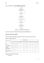
Page 85: ...e is shown as below Figure 4 1 Using SSH to login in Here presents an activity diagram user could use SSH to login in embedded Linux of BMC from remote terminal After login in successfully SMASH would...

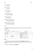
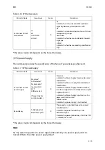
Page 86: ...mmands The system level commands provide you the information and power state control Displays information for the board show SYS Table 4 2 Targets and Verbs RELATED TARGETS SUPPORTED VERBS CD EXIT HEL...

Page 87: ...of the system chassis and main power subsystem Q A Q I tried to turn system power off by IPMI command power off when there is no response from operating system and system could not be shutdown What i...

Page 88: ...tical critical R na indicates the status not available unknown typically because system power is off ok indicates the monitored parameters within nor mal operating ranges nonCritical indicates the har...

Page 89: ...normal operat ing range critical indicates the hardware exceeding specified rat ings Table 4 7 SYS powerSupply PROPERTY NAME VALID VALUE ACCESS DESCRIPTION Sensor name list of power supply Presence F...

Page 90: ...display parameters of the management agent Displays information for the board show SP Reset BMC reset SP Set server identify LED to be off set SP ServerIdentify off Set server identify LED to be on se...

Page 91: ...ServerIdentify off on blinking R W Configuring server identify LED BMCMAC R Display the NIC physical address used by server management agent Table 4 9 SYS fan Continued PROPERTY NAME VALID VALUE ACCE...

Page 92: ...efox 8 0 and above Google Chrome 2 0 and above Login Enter the IP address or URL default DHCP static IP address into the address bar of the web browser When connecting to the BMC the Login screen prom...

Page 93: ...and Password FIELD DEFAULT Username admin Password admin Note The default username and password are in lowercase characters It is advised to change the admin password once you have logged in Table 6 M...

Page 94: ...ware version PSU0 MFR Revision Display PSU0 manufacture revision PSU0 Firmware version Display PSU0 Firmware version PSU1 MFR Revision Display PSU1 manufacture revision PSU1 Firmware version Display P...

Page 95: ...gle in the Legend for the chart allows to view a list of specific events only Server Information The Server Information Group consists of the following three items Table 8 Network Information ITEM DES...

Page 96: ...erver Information menu items Figure 4 6 Server Information Menu FRU Information In the MegaRAC GUI the FRU Information Page displays the BMC FRU file information The information displayed in this page...

Page 97: ...7 FRU Information Page A brief description of the fields is given in the following sections Basic Information Chassis Information Chassis Information Area Format Version Chassis Type Chassis Part Numb...

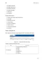
Page 98: ...anguage Manufacturer Name Product Name Product Part Number Product Version Product Serial Number Asset Tag Server Component The Component Information page displays the CPU and memory information Figur...

Page 99: ...7 Server Identify Page ITEM DESCRIPTION Current Server Identify Status The server status On or Off Server Identify Operation Server identify LED operation with the following options ON OFF Blink Serv...

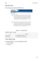
Page 100: ...OST code Figure 4 10 BIOS POST Code Server Health Group The Server Health Group consists of the following two items Sensor Readings Event Log Table 8 BIOS POST Code Page ITEM DESCRIPTION Current Codes...

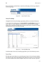
Page 101: ...nformation on a particular sensor including thresholds and a graphical representation of all associated events A screenshot of Sensor Readings page is shown in the following image Figure 4 12 Sensor R...

Page 102: ...ical going low Upper Non criti cal going high Upper Critical going low Upper Critical going high Upper Non recov erable going low Upper Non recoverable going high A graphical view of these events Numb...

Page 103: ...ou can use the sensor type or sensor name filter options to view those specific events or you can also sort the list of entries by clicking on any of the column headers To open the Event Log page clic...

Page 104: ...ll Events System Event Records BIOS Gener ated Events SMI Handler Events System Management Software Events System Software OEM Events Remote Console software Events Termi nal Mode Remote Console softw...

Page 105: ...ility to provide information on objects helps organize these objects for easy retrieval and access allows access by end users and administrators and allows the administrator to set security up for the...

Page 106: ...bols hyphen and underscore are allowed Group Name This name identifies the role group in Active Directory Note Role Group Name is a string of 64 alpha numeric characters Special symbols hyphen and und...

Page 107: ...e name that identifies the role group in the Active Directory 11 In the Role Group Domain field enter the domain where the role group is located 12 In the Role Group Privilege field enter the level of...

Page 108: ...cal naming system for comput ers services or any resource connected to the Internet or a private network It associates the information with domain names assigned to each of the participants Most impor...

Page 109: ...the device Manual and available LAN interfaces If you choose Manual setting you have to configure the DNS Server IP addresses If you have chosen DHCP then you have to select the interface from which...

Page 110: ...gned by DHCP server 6 Click Save to save the entries 7 Click Reset to reset the entries LDAP E Directory The Lightweight Directory Access Protocol LDAP is an application protocol for query ing and mod...

Page 111: ...age is given below Figure 4 21 Advanced LDAP Settings 2 To enable disable LDAP Authentication check or uncheck the Enable checkbox respectively Table 13 LDAP Settings Page ITEM DESCRIPTION Advanced Se...

Page 112: ...4 22 Add Role group Page 9 In the Role Group Name field enter the name that identifies the role group 10 In the Role Group Search Base field enter the path from where the role group is located to Base...

Page 113: ...mouse emulation from local window to remote screen in either of two methods User has to be an Administrator to configure this option To open Mouse Mode page click Configuration Mouse Mode from the ma...

Page 114: ...d to configure the network settings for the available LAN channels Save To save any changes made Reset To Reset the modified changes Note Applicable for all Windows versions RHEL Linux versions not be...

Page 115: ...Network Settings page click Configuration Network from the main menu A sample screenshot of Network Settings Page is shown in the screenshot below Figure 4 24 Network Settings Page The fields of Netwo...

Page 116: ...gs IPv6 Settings This option is to enable the IPv6 settings in the device Obtain an IPv6 address automatically This option is to dynamically configure IPv6 address using DHCP Dynamic Host Configuratio...

Page 117: ...common system failure events such as over temperature power system failure fan failure events etc Remaining entries can be made available for eOEM f or System Management Software configured events No...

Page 118: ...1 Click the Event Filter Tab to configure the event filters in the available slots Table 17 PET Management Event Filter ITEM DESCRIPTION PEF ID This field displays the ID for the newly configured PEF...

Page 119: ...Power cycle from the drop down list Choose any one of the configured alert policy number from the drop down list 5 In the Sensor configuration section Select the s type of sensor that will trigger th...

Page 120: ...y one of the Policy set values from the list 0 Always send alert to this destination 1 If alert to previous destination was successful do not send alert to this destination Proceed to next entry in th...

Page 121: ...set from the list 7 In the Channel Number field choose particular channel from the available channel list 8 In the Destination Selector field choose particular destination from the config ured destina...

Page 122: ...ion Page This page is used to configure the Event filter Alert Policy and LAN destination A sample screenshot of PEF Management LAN Destination Page is given below Figure 4 29 PEF Management LAN Desti...

Page 123: ...rs 7 In the Subject field enter the subject 8 In the Message field enter the message 9 Click Add to save the new LAN destination and return to LAN destination list 10 Click Cancel to cancel the modifi...

Page 124: ...in Configuration section 3 Select from LAN Destination menu SNMP Trap Figure 4 31 Selecting SNMP Trap A Modify LAN Destination entry menu opens 4 Key in an IP address to the Destination Address field...

Page 125: ...ngs Page are explained below Table 20 RADIUS Settings Page ITEM DESCRIPTION RADIUS Authentication Option to enable RADIUS authentication Port The RADIUS Port number Note Default Port is 1812 Time Out...

Page 126: ...al media configuration settings for the next redirection session Encryption is disabled by default To open Remote Session page click Configuration Remote Session from the main menu A sample screenshot...

Page 127: ...ch Immediately attaches Virtual Media to the server upon bootup Auto Attach Attaches Virtual Media to the server only when a virtual media session is started Save To save the current changes Note It w...

Page 128: ...alpha numeric characters Space special characters are not allowed Primary SMTP Server Lists the Primary SMTP Server configuration Server Address The IP address of the SMTP Server It is a mandatory fi...

Page 129: ...e fields 10 Click Save to save the entered details 11 Click Reset to update the entered details Username The username to access SMTP Accounts Note User Name can be of length 4 to 64 alpha numeric char...

Page 130: ...nfigure SSL certificate into the BMC Using this the device can be accessed in a secured mode To open SSL Certificate Configuration page click Configuration SSL from the main menu There are three tabs...

Page 131: ...ds of SSL Certificate Configuration Generate SSL tab are explained below Table 24 SSL Certificate Configuration Upload SSL ITEM DESCRIPTION Current Certificate Current certificate information will be...

Page 132: ...cters and are not allowed City or Locality L City or Locality of the organization mandatory Maximum length of 64 characters Special characters and are not allowed State or Province ST State or Provinc...

Page 133: ...s Version Serial Number Signature Algorithm Public Key Issued From This section describes the following Certificate Issuer information Common Name CN Organization O Organization Unit OU City or Locali...

Page 134: ...valid in the Valid For field 4 Choose the Key Length bit value of the certificate 5 Click Generate to generate the certificate 6 Click View SSL tab to view the uploaded SSL certificate in user readabl...

Page 135: ...splays the ID number of the user Note The list contains a maximum of ten users only User Name Displays the name of the user User Access To enable or disable the access privilege of the user Network Pr...

Page 136: ...cess for the user 7 Choose the SNMP Access level option for user from the SNMP Access dropdown list Either it can be Read Only or Read Write 8 Choose the Authentication Protocol to use for SNMP settin...

Page 137: ...nd message for email alert 11 In the New SSK Key field click Browse and select the SSH key file 12 Click Add to save the new user and return to the users list 13 Click Cancel to cancel the modificatio...

Page 138: ...re displayed in this page Procedure 1 Select the number of Floppy devices CD DVD devices and Hard disk devices from the dropdown list Note There is a list of reserved users which cannot be added modif...

Page 139: ...age UTC Timezone Note Maximum of two devices can be added in Floppy CD DVD and Hard disk drives Note If there are two device panels for each device and when you click the Connect button then the redir...

Page 140: ...wn list 2 Click Save to save the change else click Reset to reset the previously saved values LAN Port Settings Here you can configure LAN Port setting of the BMC NIC Figure 4 45 LAN Port Settings Tab...

Page 141: ...mote Control Menu A detailed description of the menu items are given ahead Console Redirection The remote console application which is started using the WebGUI allows you to control your server s oper...

Page 142: ...32 FC 10 64 FC 12 32 FC 12 64 FC 13 32 FC 13 64 FC 14 32 FC 14 64 MAC 32 MAC 64 List of Supported Host OS RHEL 5 RHEL 6 W2K3 W2K8 RHEL 4 OpenSuse 11 2 OpenSuse 10 x Ubuntu 8 10 Ubuntu 9 10 Ubuntu 11...

Page 143: ...va Con sole 2 Open Remote Control Console Redirection Page and click Java Console This will download the jnlp file from BMC To open the jnlp file use the appropriate JRE version Javaws When the downlo...

Page 144: ...f you disable this option the display will be back in the server screen Full Screen This option is used to view the Console Redirection in full screen mode Maximize This menu is enabled only when both...

Page 145: ...ITEM DESCRIPTION Show cursor This option is used to display or hide the client mouse cursor in Java Console Mouse calibration It is used to adjust the mouse calibration Mouse mode Absolute mouse mode...

Page 146: ...Tab to switch window Table 35 Virtual Media ITEM DESCRIPTION Floppy Key Media This menu item can be used to start or stop the redirection of a physical floppy drive and floppy image types such as img...

Page 147: ...e same then for all the languages other than English mentioned above you must select this option to avoid typo errors Soft Keyboard This option allows you to select the keyboard layout It will show th...

Page 148: ...don t wish to save the entries 7 In the Console Redirection window click Video Record Start Record 8 Record the process 9 To stop the recording click Video Record Stop Record Active Users Click this...

Page 149: ...ce tasks on the device The menu contains the following items BMC Firmware Update BIOS Update Table 38 Server Power Control ITEM DESCRIPTION Reset Server This option will reboot the system without powe...

Page 150: ...Firmware Update Page is shown in the screenshot below Figure 4 51 Firmware Update Page WARNING Please note that after entering update mode widgets other web pages and services will not work All open w...

Page 151: ...After BIOS update complete system must perform AC cycle to take effect Figure 4 52 BIOS Update Page Preserve Configuration This page allows the user to configure the preserve configuration items whic...

Page 152: ...eb UI to check SEL to be preserved Step 4 upgrade firmware Step 5 after Step 4 go to Step 2 and check if the event is still preserved if preserved then PASS else FAIL 3 IPMI Step 1 Please add a new us...

Page 153: ...KVM to be preserved Step 4 upgrade firmware Step 5 after Step 4 go to Step 2 and check if the setting is still preserved if pre served then PASS else FAIL 8 Services supported from Grantley and Micros...

Page 154: ...og out of the MegaRAC GUI click the logout link on the top right corner of the screen User Privilege Table 39 User Privilege WEB GUI PRIVILEGE LIST PRIVILEGE ASSOCIATION BETWEEN IPMI AND WEB GUI ADMIN...

Page 155: ...This page left blank intentionally...

Page 156: ...Connectors Chapter 5 This section provides guidance information for the position and configuration of con nectors...

Page 157: ...ectors 1 NIC2 1G 2 NIC1 1G 3 USB 3 0 x 2 4 COM port 5 VGA port 6 Management Port 1G 7 Riser slot1 PCIe x8 8 Mini SAS SATA 2 5 9 SATA 0 10 Mini SAS sSATA 0 3 11 Mini SAS HD PCIe x8 12 SATA 1 13 Riser s...

Page 158: ...Regulatory and Compliance Information Chapter 6 This section provides regulatory and compliance information applicable to this system...

Page 159: ......

Page 160: ......

Page 161: ......

Page 162: ......

Page 163: ......

Page 164: ......

Page 165: ...A VCCI A A...

Page 166: ...A VCCI A A...

Page 167: ......

Reviews: