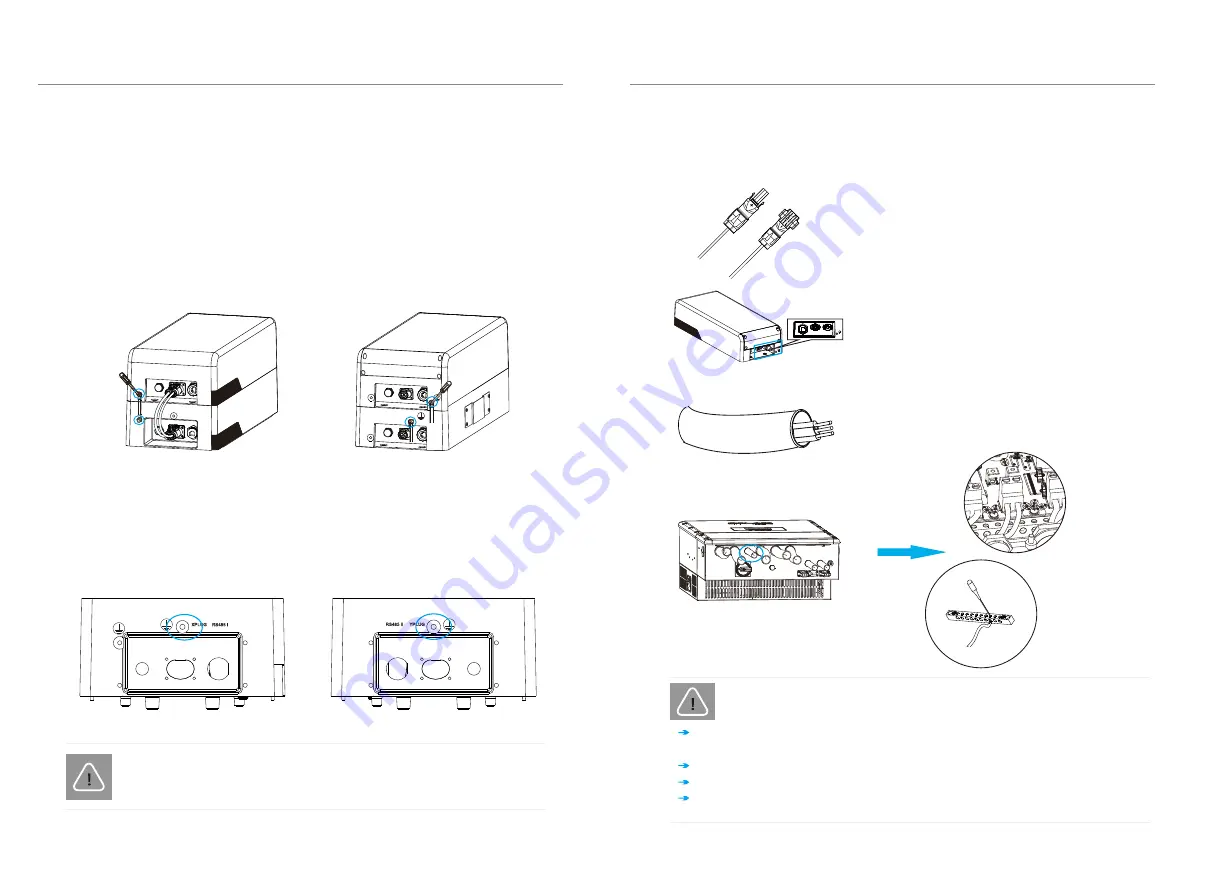
below
(1)
(2)
connect the ground wire from this battery to the next one as shown in the
picture
GND
Charging Cables
4. Installation
4. Installation
26
27
4.5.4
Connecting the
Ground Wire
For one battery module:
Unscrew the ground terminal with a hexagon wrench on the
BMS and battery module
on both sides of the ground port as marked in the figure below.
1) On one side, connect the ground wire from the BMS to the battery module
Note: 10AWG ground wire is required for grounding
For 2
-
3 battery modules:
The GND connection between the BMS and battery module is the same as
described above.
The terminal point for the GND connection on the battery modules is marked as
below.
Left side of a battery module
Right side of a battery module
1) Connect the charging cables between the
inverter and BMS. Ensure that the charging cables
(+,-) are connected to the correct port on both the
inverter and BMS.
2) Connect the negative cable (-) (B) to the port
on the right and the positive cable (+) (A) to
the port on the left.
4.5.5
Connecting the
Charging Cables
This step details instructions on connecting the charging cables with the inverter
+
and the
Q.HOME BAT-G1 system.
When connecting the cable to the BMS, fit the two connectors together until
the connection audibly locks into place.
Check to make sure the connection is securely locked.
Do not shake the ends of the cables at the joint once the connection is locked.
3) Place
the other end of the
charging cable and the
GND through the conduit. Insert the tripped end
of
each
wire into the holes, then tighten each screw.
CAN
BAT
+ -
CAUTION!
The GND connection is mandatory.
NOTE!
INSTALLATION AND OPERATION MANUAL LITHIUM-ION BATTERY – Q CELLS
2) On the other side, connect the ground wire from the
BMS to the inverter, and
INSTALLATION AND OPERATION MANUAL LITHIUM-ION BATTERY – Q CELLS
To dismantle the charging cable, use a slotted screwdriver; do not try to unplug
with brute force.


