background image

Q-SEE QUICK INSTALLATION GUIDE 

M

M

O

O

D

D

E

E

L

L


N

N

U

U

M

M

B

B

E

E

R

R


Q

Q

T

T

4

4

2

2

6

6

-

-

8

8

1

1

1

1


4 | P a g e  

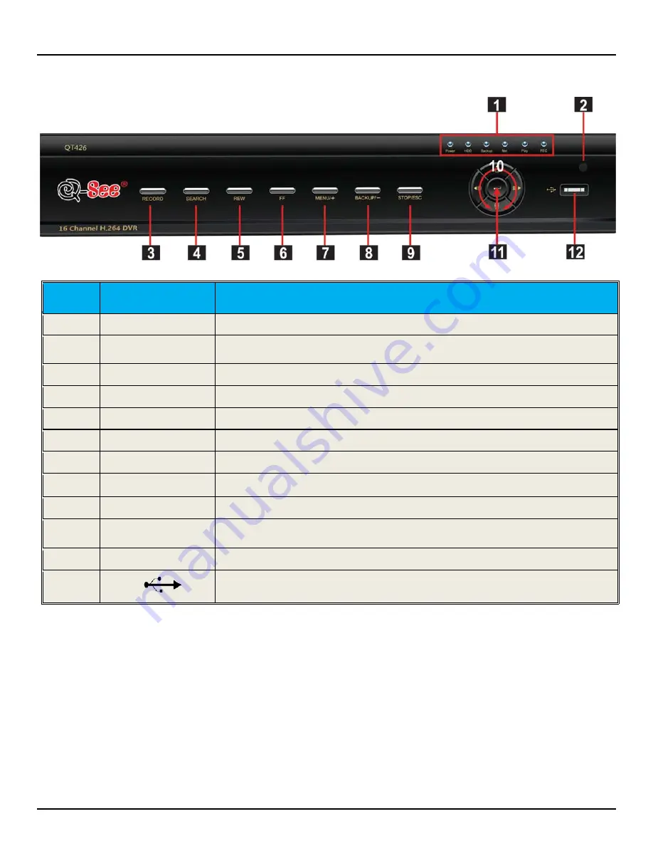
PART 4 - DVR CONTROLS: FRONT PANEL 


Item 

Number 

Name/Symbol 

Description 

LED INDICATORS 

Working indicators for power, HDD, NET, etc 

POWER 

Power On/Off 

RECORD 

Record Manually 

PLAY/SEARCH 

Enter Play Interface/Search Files 

REW 

Rewind Key 

FF 

Fast Forward 

+/MENU 

Increase the value in setup/Enter menu in live view 

/BACKUP 

Decrease the value in setup/Enter backup mode in live view 

STOP/ESC 

Quit play mode/Exit the current interface or status 

10 

DIRECTION/ 

MULTISCREEN 

1.Change direction to select items  
2. Change screen display mode from 1/4/9/16 channel 

11 

ENTER 

Confirm selection 

12 


To connect external USB devices like USB flash, USB HDD for backup or update 
firmware 


Summary of Contents for QT426-811

Page 1: ...Quick Installation Guide 16 Channel H 264 Compression DVR with CIF Real Time Recording and 8 Color CMOS Camera Kits M MO OD DE EL L Q QT T4 42 26 6 8 81 11 1...

Page 2: ...lor CMOS Cameras with Stands 4 QSM1424C 6mm Lens 4 QSM1424W 3 6mm Lens Remote Control USB 2 0 Mouse Ethernet Cable BNC M RCA F Adapter Camera Cables 8 Included Power Supply 8 Way Splitter For Cameras...

Page 3: ...26 6 8 81 11 1 2 P a g e PART 2 DVR CAMERA AND POWER CONNECTIONS Please note that it is STRONGLY recommended to use a surge protector that is UL 1449 rated Look for a clamping voltage of 330 or lower...

Page 4: ...A port on the DVR 2 Connect the other end of the VGA cable not included to a VGA monitor 3 Go to the login screen on the VGA monitor and log in to the DVR 4 Attach the RCA cable from the DVR to the RC...

Page 5: ...H Enter Play Interface Search Files 5 REW Rewind Key 6 FF Fast Forward 7 MENU Increase the value in setup Enter menu in live view 8 BACKUP Decrease the value in setup Enter backup mode in live view 9...

Page 6: ...en in Pic 5 3 Click on the Setup icon Red box in Pic 5 3 to access the Setup Menu shown as Pic 5 4 Pic 5 2 Pic 5 3 This is the section of the menu where you go to setup the main functions of the DVR I...

Page 7: ...to sections 4 4 3 through 4 5 1 of the user s manual for information on how to set these up To setup any type of recording you need to select Record in the Setup menu RED square in Pic 6 1 which will...

Page 8: ...ing 2 Time Schedule Recording Follow instructions in Part 5 to go to Setup menu Click on the Schedule icon Green box in Pic 6 4 This will display the screen in Pic 6 5 Go to the Schedule Tab highlight...

Page 9: ...n the camera and the level of sensitivity you want for the camera When you select the setting option it will open the screen shown in Pic 6 9 If you click on the star icon Green box in Pic 6 9 the ent...

Page 10: ...as Pic 7 2 There are 3 search tabs in this dialog box Time Search Event Search and File Manager Pic 7 1 TO SEARCH BY TIME Go to the Time Search tab Blue tab in Pic 7 2 Select a channel and display mod...

Page 11: ...mark the motion alarm or all option Double click on the file you would like to playback the file will play and the control panel shown in Pic 7 3 will be displayed Pic 7 4 FILE MANAGER You can also go...

Page 12: ...nd window Put a checkmark in the box on the left side of the channel number for the file or files you want to backup or put a checkmark in the All box on the bottom of the window to select the files t...

Page 13: ...omments Contact Us Mailing Address Customer Service DPS Inc Phone 877 998 3440 x 538 8015 E Crystal Dr Email cs dpsi usa com Anaheim CA 92807 Live Chat from our Website Website Tech Support http www q...

Reviews: