background image

10

When installing your camera, it is important to select a proper site not only for field 
of view, but for other considerations as well:

Distance from viewing/recording device.

 The further the camera is from the DVR or 

monitor, the higher the chances of signal degradation. Typical 75Ω Video Cable 

provides acceptable signal at distances up to 200’ (30m). At greater distances, 

UL-Listed shielded RG59 should be used. The camera’s power supply should be 

located as near to the camera as possible when the distance exceeds 200’ as 
the power level will drop over extended distances resulting in a decrease in video 
quality.

Do not place near high voltage wires or other sources of electrical interference.

 Electrical 

interference will degrade the quality of the signal. 

Place camera out of reach to avoid damage.
Avoid direct exposure to weather.

 Do not place the camera where rain or snow will 

hit the lens directly nor should the camera be placed so that the sun or bright light 
shines directly into the lens. Your camera is weatherproof, but it will not work when 
submerged in water. Ensure that all power and video connections are not directly 
exposed to water and are protected from the elements.

Do not place camera behind a window.

 If there is a light source behind the camera, it 

can cause a reflection in the window that will obscure events on the other side of 

the glass. 

Light levels should be approximately the same between camera and target area.

 A 

camera in a brightly-lit area looking into a shaded area, or vice versa, may produce 
inadequate results.
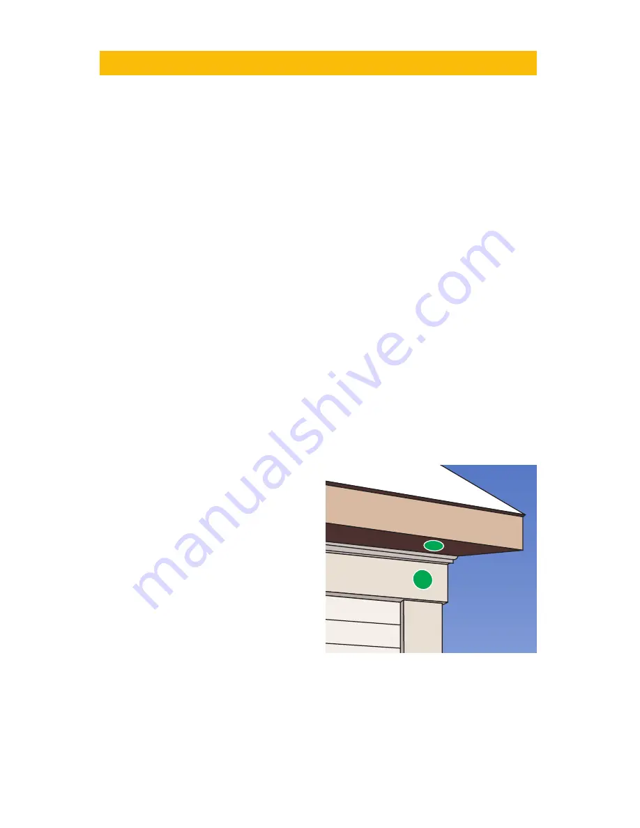
The above are guidelines and the optimal location for your camera will depend on 

INSTALLING THE CAMERA

your unique circumstances. As a general 
rule, the locations highlighted in green in 
the picture to the right indicate the best 
locations to mount your camera. Both 
locations are sheltered from rain or snow 
and offer good sight lines to allow your 
camera to monitor a wide area. Because 
your camera is weatherproof, it requires 
less protection than weather-resistant 
cameras and it can be placed in more 
exposed locations if needed. Keep in 
mind that this camera is designed to 
operate between 

14°F to 122°F (-10°C 

to 50°) with a relative humidity of up to 

95%) and consider wind chill and other environmental factors when selecting your 
location.
Your camera comes with both a ceiling and wall mount. Where you locate your 
camera will determine which mount you will need to use. The mounting surface 
must be sturdy and able to hold at least five times the camera’s total weight.

Summary of Contents for QD7015P

Page 1: ...1 QD7015P USER MANUAL ...

Page 2: ...ss of its contents Manufacturer shall not be liable for any damages whatsoever from misuse of this product Thank You for Choosing a Q See Product All of our products are backed by a conditional service warranty covering all hardware for 24 months from the date of purchase Additionally our products also come with a free exchange policy that covers all manufacturing defects for one month from the da...

Page 3: ...y policy What doesn t my warranty cover Your warranty doesn t cover the following Misuse Accident Modification or alteration to hardware or software including the removal of any Q See logos or brand identification Cut or spliced cables or wires Products that have been painted Wires coated in insulation caulk or other materials Tampering or unauthorized repairs Unsuitable physical or operating envi...

Page 4: ...going effort to constantly improve our products additional features and functions may have been added since that time and on screen displays may change We encourage you to visit our website at www Q See com to check for the latest product announcements You can also find technical details and an electronic version of this manual on our online Knowledge base online at www Q See com support Throughou...

Page 5: ...otation tilt speed 13 second n Decoder s all in one integrated design ensures high reliability n Camera can be controlled with an optional keyboard Image Sensor 1 3 Sony Exview HAD CCD II Digital Signal Processor Sony Effio E Signal System NTSC or PAL models Lens 6mm Scanning 2 1 Interlace Sync System Internal Horizontal System 700TVL 960H Effective Pixels HxV NTSC 976x494 PAL 976x582 Shutter Spee...

Page 6: ...s case please make a temporary connection by following the procedures laid out in the next section Connecting the Camera Please be advised that adjusting these settings after the camera is mounted can be difficult due to the panel potentially being inaccessible because of location position etc To access the panel remove the clear dome by first twisting the collar around the dome counterclockwise T...

Page 7: ...settings Address Switch 8 digits Code 1 2 3 4 5 6 7 8 1 1 0 0 0 0 0 0 0 2 0 1 0 0 0 0 0 0 3 1 1 0 0 0 0 0 0 4 0 0 1 0 0 0 0 0 5 1 0 1 0 0 0 0 0 6 0 1 1 0 0 0 0 0 7 1 1 1 0 0 0 0 0 8 0 0 0 1 0 0 0 0 9 1 0 0 1 0 0 0 0 10 0 1 0 1 0 0 0 0 11 1 1 0 1 0 0 0 0 12 0 0 1 1 0 0 0 0 13 1 0 1 1 0 0 0 0 14 0 1 1 1 0 0 0 0 15 1 1 1 1 0 0 0 0 16 0 0 0 0 1 0 0 0 Address EXAMPLE The illustration below shows the se...

Page 8: ... can support PTZ operations There are three sets of connectors power video and the bare control wires This latter connection is covered on the next page We recommend connecting the camera at least temporarily to the DVR to test your settings and connections before mounting it in its final location AUDIO IN VIDEO IN 1 3 2 4 1 3 2 4 POWER AND VIDEO CONNECTION IMPORTANT When connecting the power and ...

Page 9: ...l clamp will keep the wire firmly secured in the port If the wire can easily be removed from the port then it isn t secure and you can experience control difficulties until it is properly attached Serial Port Serial Port Advanced Advanced P T Z P T Z Default Default Apply Apply Exit Exit CH Enable Address Baud Rate Protocol Simulative Cruise 1 2 3 4 CH Enable Address Baud Rate Protocol Simulative ...

Page 10: ... protected from the elements Do not place camera behind a window If there is a light source behind the camera it can cause a reflection in the window that will obscure events on the other side of the glass Light levels should be approximately the same between camera and target area A camera in a brightly lit area looking into a shaded area or vice versa may produce inadequate results The above are...

Page 11: ...ounting holes and mount the bracket to the surface STEP 5 Pass the cable ends from the camera through the hole at the front of the bracket the green block should be passed through the hole first STEP 6 Connect the camera s cable ends to those on the extention cable STEP 7 Secure the camera to the mount using the three short bolts STEP 8 Make sure that the cables aren t crimped inside the bracket a...

Page 12: ... enhanced by using shielded cables Always check state and local laws before installing cameras 2011 NEC 820 44 To prevent video signal loss run one continuous cable between the camera and DVR for best results If more length is required use the minimum number of inter connection points possible Other notes If a cable run exceeds 800ft we recommend using RG 6 coaxial cable which is available at most...

Page 13: ...ing that point Then by selecting one or more points for the camera to move to in sequence a scan path is built which is then saved Often multiple paths can be saved within the DVR which can be selected for later use These points can be set using a special PTZ keyboard or by using the PTZ controls on the DVR itself Two such on screen interfaces are shown at right the QT Series top and QC series bot...

Page 14: ...ng Setting Setting Setting Setting Setting Setting Setting Setting Setting Setting Setting Setting Setting Setting Setting Setting Setting Setting Setting Setting Setting Setting Apply Apply Exit Exit CH Preset Cruise Track 1 2 3 4 5 6 7 8 CH Preset Cruise Track 1 2 3 4 5 6 7 8 Save Save Zoom Focus Iris Zoom Focus Iris Speed 5 Speed 5 No No 1 1 02 02 01 01 03 03 04 04 05 05 06 06 07 07 08 08 All A...

Page 15: ...n screen image is dim 1 Check for fingerprints or dirt on the lens 2 Check monitor settings The on screen image is dark 1 Adjust the monitor contrast settings The screen flickers Camera may be facing sun television or computer monitor The camera is not working properly is hot smells or is producing smoke DISCONNECT CAMERA FROM POWER SUPPLY IMMEDIATELY 1 Check that correct power supply is in use 2 ...

Page 16: ...16 ...

Reviews: