background image

6.2

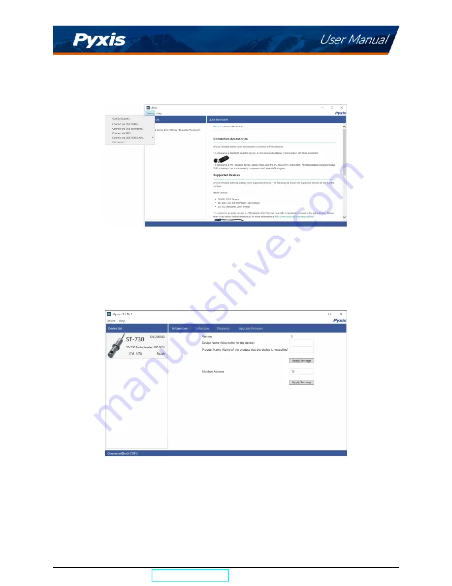
Connecting to uPyxis® Desktop App

When the

uPyxis®

Desktop App opens, to find your device, click on

Device

, then

Connect via USB-RS485

.

Figure 13.

6.3

Information Screen

Once connected to the device, a picture of the device will appear on the top left corner of the window and
the

uPyxis®

Desktop App will default to the

Information

screen. On the

Information

screen you can set the

information description for

Device Name

and

Product Name

, then click

Set

to save.

Figure 14.

ST-730 Series User Manual

[email protected]

| +1 (866) 203-8397

12

Summary of Contents for 50626

Page 1: ......

Page 2: ...Series Inline Turbidity Sensors User Manual January 22 2021 Rev 1 34 Pyxis Lab Inc 1729 Majestic Dr Suite 5 Lafayette CO 80026 USA www pyxis lab com 2017 Pyxis Lab Inc Pyxis Lab Proprietary and Confid...

Page 3: ...ing to uPyxis Mobile App 9 5 3 Calibration Screen and Reading 10 5 4 Diagnosis Screen 10 5 5 Device Info Screen 11 6 Setup and Calibration with uPyxis Desktop App 11 6 1 Install uPyxis Desktop App 11...

Page 4: ...very All service interventions are to be reviewed and authorized as correct and complete at the completion of the service by a customer representative or des ignate Pyxis warrants these services for 3...

Page 5: ...the MA WB Bluetooth adapter and uPyxis Mobile or Desktop App 2 Specifications Table 1 ST 730 ST 730B ST 731 and ST 735 Specifications Specifications ST 730 ST 730B ST 731 ST 735 Part Number P N 53201...

Page 6: ...50 F 7 66 C Pressure Up to 290 psi 2 0 MPa at 149 F 65 C Enclosure Rating IP66 Regulation CE With Pyxis s continuous improvement policy these specifications are subject to change without notice 3 Unpa...

Page 7: ...ies The following optional accessories can be ordered from Pyxis Customer Service order pyxis lab com or Pyxis E Store at https pyxis lab com shop Figure 1 ST 730 Series User Manual service pyxis lab...

Page 8: ...730 730B 731 735 sensor into the ST 001 Tee Assembly follow the steps below 1 Insert the provided O ring into the O ring groove on the tee 2 Insert the ST 730 730B 731 735 sensor into the tee 3 Tighte...

Page 9: ...a custom tee assembly It is recommended that two 3 4 NPT to 1 4 tubing adapters are used to connect the sensor to the sampling system Sample water entering the sensor must be cooled down to below 120...

Page 10: ...ed 24V Black 24V Power ground White 4 20mA Green 4 20mA Blue RS 485 A Yellow RS 485 B Clear Shield earth ground Internally connected to the power ground 4 4 Connecting via Bluetooth A Bluetooth adapte...

Page 11: ...rs may result in permanent damage of the ST 730 Series sensor communication hardware Figure 6 USB connection to ST 730 Series sensor 5 Setup and Calibration with uPyxis Mobile App 5 1 Download uPyxis...

Page 12: ...1 Open uPyxis Mobile App 2 On uPyxis Mobile App pull down to refresh the list of available Pyxis devices 3 If the connection is successful the ST 730 Series and its Serial Number SN will be displayed...

Page 13: ...alibration Slope Calibration and 4 20mA Span Follow the screen instructions for each calibration step Figure 9 5 4 Diagnosis Screen From the Diagnosis screen you can check the diagnosis condition as w...

Page 14: ...nload and install the Microsoft Net Framework 4 5 if not previously installed on the PC the USB driver for the USB Bluetooth adapter MA NEB the USB RS485 adapter MA 485 and the main uPyxis Desktop app...

Page 15: ...Once connected to the device a picture of the device will appear on the top left corner of the window and the uPyxis Desktop App will default to the Information screen On the Information screen you c...

Page 16: ...y 4 seconds Follow the screen instructions for each calibration step Figure 15 6 5 Diagnosis Screen After the device has been calibrated and installation has been completed to check diagnosis click on...

Page 17: ...The 4 20mA output of the ST 730B sensor is scaled as Turbidity 4 mA 0 NTU 20 mA 1 000 NTU The 4 20mA output of the ST 731 sensor is scaled as Turbidity 4 mA 0 NTU 20 mA 10 NTU The 4 20mA output of th...

Page 18: ...ktop App click 4 20mA Span found on the Cali bration Screen shown in Figure 18 Figure 17 Figure 18 7 3 Communication using Modbus RTU The ST 730 Series sensor is configured as a Modbus slave device In...

Page 19: ...s below have been shown to remove most common foulants and contaminants A small soft bristle brush Q Tips cotton swab or soft cloth may be used to safely clean the sensor housing and the quartz optica...

Page 20: ...adjacent to the ST 730 Series tee Carry out routine calibration verification against a qualified turbidity standard After properly cleaning the ST 730 Series sensor carry out the zero point and slope...

Reviews: