7
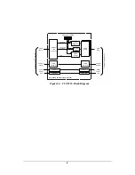
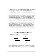
retransmitted to the Camera Link
TM
camera using LVDS signaling. When the CLT-
351R/L is operated in one of the single-channel modes (1x8, 1x10, 1x12, 1x14, 1x16), all
four camera control signals are received from the frame grabber and routed to the camera.
In the dual-channel (2x8, 2x10, 2x12) and color (3x8) modes, the number of camera
control lines in the frame grabber’s AIA interface is reduced to allow for added pixel data.
In dual-channel and color modes, only one camera control signal (CC1) is supported.
The CLT-351R/L routes the serial communication signals between the camera and the
frame grabber. This supports host computer access to mode control and status registers in
the Camera Link
TM
camera via the serial link built-into the AIA interface. The CLT-
351R/L camera interface incorporates LVDS devices for the serial communication signals.
The frame grabber interface serial signals are implemented using LVDS or RS-422
devices, depending on CLT-351 version.
The CLT-351R/L is powered by an external wall plug-in power supply (included).
Summary of Contents for CAMERA LINKT CLT-351L
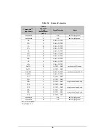
Page 21: ...19 Ground 68 N A tied to digital ground 1 Pixel Data MSB FG Frame Grabber ...
Page 24: ...22 Ground 68 N A tied to digital ground 1 Pixel Data MSB FG Frame Grabber ...
Page 27: ...25 Ground 68 N A tied to digital ground 1 Pixel Data MSB FG Frame Grabber ...
Page 30: ...28 Ground 68 N A tied to digital ground 1 Pixel Data MSB FG Frame Grabber ...
Page 33: ...31 Ground 68 N A tied to digital ground 1 Pixel Data MSB FG Frame Grabber ...
Page 36: ...34 Ground 68 N A tied to digital ground 1 Pixel A MSB 2 Pixel B MSB FG Frame Grabber ...
Page 39: ...37 Ground 68 N A tied to digital ground 1 Pixel A MSB 2 Pixel B MSB FG Frame Grabber ...
Page 42: ...40 Ground 68 N A tied to digital ground 1 Pixel A MSB 2 Pixel B MSB FG Frame Grabber ...


