8
1.3.1.
Mode Switch Settings
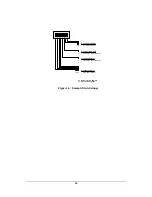
The CLT-351R/L incorporates a rear-panel mode select switch. The switch allows
the user to identify pixel data, timing signal, and clock characteristics. The mode
switch has eight positions. The functional assignments are defined in Figure 1-4.
1 2 3 4 5 6 7 8
0 0
0 1
1 1
1 0
- 0
o
(most common)
- 90
o
- 180
o
- 270
o
Clock Phase Shifter
Frame Valid Polarity
0
1
- active-high (most common)
- active-low
0 = "down" switch position
1 = "up" switch position
Line Valid Polarity
0
1
- active-high (most common)
- active-low
0 0 0 0
0 0 0 1
0 0 1 0
0 0 1 1
0 1 0 0
1 0 0 0
1 0 0 1
1 1 0 1
1 1 0 1
- 8-bit, single-channel
- 10-bit, single-channel
- 12-bit, single-channel
- 14-bit, single-channel
- 16-bit, single-channel
- 8-bit, dual-channel
- 10-bit, dual-channel
- 12-bit, dual-channel
- 8-bit, color (8x3)
Pixel Data Format
Figure 1-4: CLT-351R/L Mode Switch Definition
Summary of Contents for CAMERA LINKT CLT-351L
Page 21: ...19 Ground 68 N A tied to digital ground 1 Pixel Data MSB FG Frame Grabber ...
Page 24: ...22 Ground 68 N A tied to digital ground 1 Pixel Data MSB FG Frame Grabber ...
Page 27: ...25 Ground 68 N A tied to digital ground 1 Pixel Data MSB FG Frame Grabber ...
Page 30: ...28 Ground 68 N A tied to digital ground 1 Pixel Data MSB FG Frame Grabber ...
Page 33: ...31 Ground 68 N A tied to digital ground 1 Pixel Data MSB FG Frame Grabber ...
Page 36: ...34 Ground 68 N A tied to digital ground 1 Pixel A MSB 2 Pixel B MSB FG Frame Grabber ...
Page 39: ...37 Ground 68 N A tied to digital ground 1 Pixel A MSB 2 Pixel B MSB FG Frame Grabber ...
Page 42: ...40 Ground 68 N A tied to digital ground 1 Pixel A MSB 2 Pixel B MSB FG Frame Grabber ...

