Precision Valve & Automation
One Mustang Drive
Cohoes, NY 12047
www.pva.net
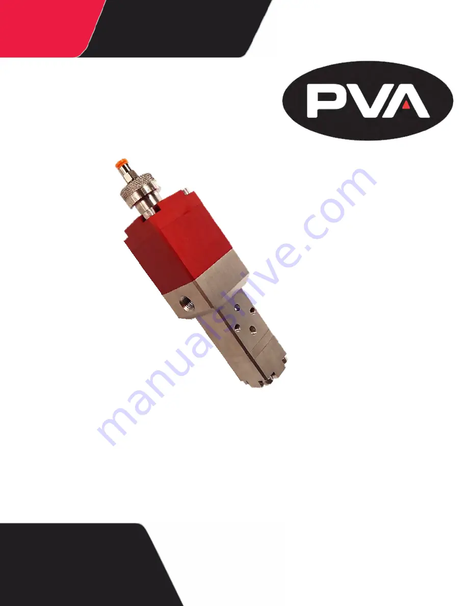
SB300 Valve
OWNER’S MANUAL
Rev A
WHERE
PRECISION
DRIVES
PRODUCTION
Page 1: ...Precision Valve Automation One Mustang Drive Cohoes NY 12047 www pva net SB300 Valve OWNER S MANUAL Rev A WHERE PRECISION DRIVES PRODUCTION ...
Page 2: ...anges subsequently made Precision Valve and Automation Inc makes no representation or warranty expressed implied or statutory with respect to and assumes no responsibility for the accuracy completeness sufficiency or usefulness of the information contained herein No warranties of merchantability or fitness for purpose shall apply This document including the information contained herein is the prop...
Page 3: ...ed the Valve 9 4 1 Shutdown 10 4 3 Maintenance 11 5 Valve Lubricant 11 5 1 Disassembly 11 5 2 Clean the Valve Components 22 5 3 End Cap 22 5 3 1 Fluid Body 23 5 3 2 Separation Body 23 5 3 3 Air Cylinder 23 5 3 4 Air Cap 24 5 3 5 Assemble the Valve 24 5 4 To Replace O rings 39 5 5 To Replace Lip Seals 40 5 6 Exploded View 41 6 Exploded View of the NPT Version 41 6 1 Item Numbers and Descriptions fo...
Page 4: ... View of the Luer Version 43 6 3 Item Numbers and Descriptions for 112 07384 Luer version 44 6 4 Technical Specifications 45 7 Troubleshooting 46 8 Notes 47 9 Warranty 48 10 Table of Figures 49 11 REVISION A 2014 4 of 50 ...
Page 5: ...rive Cohoes NY 12047 Tel 1 518 371 2684 Fax 1 518 371 2688 Website http www pva net Email mailto info pva net Technical Support Tel 1 518 371 2684 Email mailto cs pva net Document History 2 2 Revision Revision Date Reason for Changes REV A April 2014 Initial Release NOTE All photographs and CAD model representations in this document are a general representation of the valve and its components The ...
Page 6: ...and understand the manuals provided with the unit Never put hands or tools in areas with this symbol when the machine is in operation A dangerous condition may exist Read and understand the manuals provided with the unit before any repairs or maintenance is done Only a qualified individual should do service Use caution when there are pressurized vessels Find and repair any leaks immediately Always...
Page 7: ...rotection because material contents are under pressure Always wear gloves when handling materials and solvents Refer to MSDS sheets on the material being dispensed for other precautions Waste Disposal 2 6 Dispose of all used parts and materials in accordance with local laws and regulations Necessary Tools 2 7 PVA offers tools and cleaning accessories to maintain the SB300 valve Part Number Descrip...
Page 8: ...elow for safe and correct operation 1 Make sure your valve is correctly connect to the dispense system Refer to your fluid schematic 2 Make sure you know the valve specifications and do not operate the valve outside of the specifications Overview 3 1 Figure 1 Valve Components REVISION A 2014 8 of 50 ...
Page 9: ... the stroke adjust clockwise until it is fully engaged 3 Then turn the stroke adjust counterclockwise to loosen it until the material dispenses without any breaks in the flow of material 4 Release the purge button NOTE If the material has drips or strings after dispensing there is still air in the valve and it must be bled again 5 After the valve has been correctly bled continue with normal operat...
Page 10: ...ack and turn the stroke adjust clockwise to decrease snuff back 4 If you cannot get the necessary results turn the stroke adjust counterclockwise until it is fully loosened Some applications work best this way Decrease the snuff back as necessary Figure 3 Stroke Adjust Fully Loosened Shutdown 4 3 1 Release the pressure in the system refer to the workcell manual 2 Open the valve and let any materia...
Page 11: ...ubricated Removable thead locker must be applied to the set screw that goes on the piston Valve Lubricant 5 1 There are three different kinds of lubricants used on this valve Lubricant This is used on many of the O rings and lip seals for lubrication and to improve the seal Grease This is applied to many of the air section components Oil This is used on the threads of the stroke adjust to make sur...
Page 12: ...on the air and fluid sections to separate the sections Figure 5 Air and Fluid Sections Separated 6 Use a hex wrench to remove the four separation body screws 14 Figure 6 Remove the Four Screws 7 Remove the separation body 6 from the fluid body 7 REVISION A 2014 12 of 50 ...
Page 13: ... the pick to remove the lip seal 11 Figure 8 Remove the Lip Seal 9 Use the pick to remove the O ring 22 Figure 9 Remove the O ring 10 Use a hex wrench to remove the end cap screws 16 For valves with a luer outlet continue to step 13 REVISION A 2014 13 of 50 ...
Page 14: ...ons 12 Use a pick to remove the O ring 21 Figure 12 Remove the End Cap O ring Continue to step 19 for valves with the 1 4 NPT end fitting For For valves with a luer outlet NOTE part numbers for steps 13 18 refer to drawing number 112 07384 13 Use a hex wrench to remove the end cap screws 16 REVISION A 2014 14 of 50 ...
Page 15: ...rate the end cap 3 from the seal plate 1 Figure 14 Separate the End Cap from the Seal Plate 15 Use a wrench to loosen and remove the luer adaptor 20 Figure 15 Remove the Luer Adaptor 16 Use a pick to remove the washer 19 from the end cap 3 REVISION A 2014 15 of 50 ...
Page 16: ...ng 23 from the end cap 3 Figure 17 Remove the O ring from the End Cap Do the steps below for both valve types 18 Separate the seal plate 1 from the fluid body 7 Figure 18 Separate the Seal Plate from the Fluid Body 19 Use a pick to remove the seal plate O ring 22 REVISION A 2014 16 of 50 ...
Page 17: ...o remove the lip seal 12 from the seal plate 1 Figure 20 Remove the Lip Seal 21 Use a pick to remove both of the washers 2 from the fluid body 7 Figure 21 Washers in the Fluid Body 22 Separate the air cap 5 from the air cylinder 3 REVISION A 2014 17 of 50 ...
Page 18: ...mbly from the air cylinder 3 Pull the piston rod assembly out of the air cylinder Figure 23 Remove the Piston Rod Assembly 24 Pull the spring 18 out of the air cylinder 3 Use a pick if necessary Figure 24 Remove the Spring 25 Use a pick to remove the air cylinder O ring 19 REVISION A 2014 18 of 50 ...
Page 19: ...4 Figure 26 Remove the Piston O ring 27 Use a hex wrench to remove the set screw 15 in the piston 4 Hold the flat section on rod 8 with a wrench and turn the set screw until it is loose Figure 27 Disassemble the Piston Rod Assembly 28 Disassemble the piston rod assembly REVISION A 2014 19 of 50 ...
Page 20: ... disassembly procedure If it is necessary to disassemble the air cap 5 and stroke adjust 9 do the steps below 30 Turn the stroke adjust 9 so that the threads can be seen at the bottom of the air cap 5 31 Use snap ring pliers to remove the snap ring 13 from the stroke adjust 9 Figure 29 Snap Ring Removed REVISION A 2014 20 of 50 ...
Page 21: ...clockwise to loosen the stroke adjust until it is removed from the air cap 5 Figure 30 Stroke Adjust Removed from Air Cap 33 Remove the O ring 20 from the stroke adjust 9 Figure 31 Remove the O ring from the Stroke Adjust REVISION A 2014 21 of 50 ...
Page 22: ...ine and clean all of the O rings 19 20 21 22 23 24 2 If there is any wear or damage replace the O ring Figure 32 Examine O rings 3 Examine and clean the lip seals 11 12 4 It they are damaged or show wear replace the lip seals Figure 33 Examine Lip Seals End Cap 5 3 1 Clean the end cap 10 Use cotton tipped swabs lint free wipes and solvent Figure 34 Clean End Cap REVISION A 2014 22 of 50 ...
Page 23: ...re 35 Clean the Fluid Body Separation Body 5 3 3 Clean the separation body 6 Use cotton tipped swabs lint free wipes and solvent Figure 36 Clean the Separation Body Air Cylinder 5 3 4 Clean the Air Cylinder 3 Use cotton tipped swabs lint free wipes and solvent Figure 37 Air Cylinder REVISION A 2014 23 of 50 ...
Page 24: ...Assemble the Valve 5 4 Do the steps below to assemble the valve after it has been cleaned If you disassembled the air cap 5 and stroke adjust 9 put it together again 1 Install the O ring 20 on the stroke adjust 9 Figure 39 Install the Stroke Adjust O ring 2 Apply grease to the inside of the air cap 5 REVISION A 2014 24 of 50 ...
Page 25: ... Figure 41 Apply Oil to the Stroke Adjust Threads 4 Apply grease to the stroke adjust O ring 20 Figure 42 Apply Grease to the O ring 5 Install the stroke adjust 9 into the air cap Turn the stroke adjust clockwise until it is engaged and the threads can be seen coming through the air cap 5 REVISION A 2014 25 of 50 ...
Page 26: ...nstall the Snap Ring 7 Turn the stroke adjust 9 counterclockwise to decrease the threads the show on the bottom of the air cap 5 8 Install the O ring 23 on the air cap 5 Figure 45 Install the Air Cap O ring 9 Apply grease to the air cylinder 3 and use the dispense tip to make an even layer REVISION A 2014 26 of 50 ...
Page 27: ...iston 4 rod 8 set screw 15 and O ring 24 Figure 47 Piston Rod Assembly Components 11 Apply removable thread locker to the set screw 15 Figure 48 Apply Removable Thread Locker 12 Put the rod 8 on the side of the piston 4 with the groove in it REVISION A 2014 27 of 50 ...
Page 28: ... tighten the screw Hold the flat section of the rod 8 with a wrench and make sure the screw is fully engaged in the piston 4 with the hex wrench Figure 50 Piston Rod Assembly 14 Install the piston O ring 24 Figure 51 Install the Piston O ring 15 Apply grease to the piston O ring 24 REVISION A 2014 28 of 50 ...
Page 29: ... cylinder 3 18 Hold the air cylinder 3 in one hand and pull down on the rod 8 until the piston 4 is below the edge of the air cylinder 19 Put the air cylinder O ring 19 on your finger and apply grease to Squeeze the O ring between two fingers to coat the O ring with grease REVISION A 2014 29 of 50 ...
Page 30: ... cylinder 3 Figure 53 Rod O ring Installed 21 Install the lip seal 11 in the separation body 6 You should be able to see the O ring in the lip seal when it is installed correctly Figure 54 Lip Seal Installed in the Separation Body 22 Apply lubricant to the top of the lip seal 11 REVISION A 2014 30 of 50 ...
Page 31: ...a small amount of lubricant to the lowest edge inside the fluid body Do this for both sides Figure 56 Apply Lubricant to the Fluid Body 24 Install the washer 2 in the fluid body Do this for both sides Figure 57 Install the Washers in the Fluid Body REVISION A 2014 31 of 50 ...
Page 32: ...O ring 26 Apply lubricant to the O ring 22 27 Put the fluid body 7 on the separation body 6 Figure 59 Separation Body and Fluid Body 28 Install the separation body screws 14 and tighten them equally with a hex wrench Make sure the components are aligned REVISION A 2014 32 of 50 ...
Page 33: ... 12 in the seal plate 1 The O ring should be seen when the lip seal is correctly installed Figure 61 Lip Seal Install O ring Up 30 Apply lubricant to the lip seal 12 Figure 62 Apply Lubricant to the O ring 31 Install the O ring 22 in the seal plate 1 REVISION A 2014 33 of 50 ...
Page 34: ...icant to the O ring 22 in the seal plate 1 Figure 64 Apply Lubricant to the Seal Plate O ring 33 Install the seal plate 1 on top of the fluid body 7 Figure 65 Install the Seal Plate 34 Apply lubricant to the O ring groove in the end cap 10 REVISION A 2014 34 of 50 ...
Page 35: ...roove 35 Install the O ring 21 in the end cap 10 Figure 67 End Cap O ring Installed 36 Apply lubricant to the end cap O ring 21 Figure 68 Apply Lubricant to the End Cap O ring 37 Install the end cap 10 on top of the seal plate 1 REVISION A 2014 35 of 50 ...
Page 36: ...Install the end cap screws 16 Use a hex wrench to tighten them equally Figure 70 Tighten the End Cap Screws Equally 39 Make sure the valve is correctly aligned Figure 71 Sections Aligned 40 Apply lubricant to the rod 8 REVISION A 2014 36 of 50 ...
Page 37: ... the separation body 6 so that it is engaged in the rest of the valve Figure 73 Install the Rod into the Fluid Section 42 When the rod 8 is installed to the where there is resistance use a press to fully engage the rod in the fluid section of the valve REVISION A 2014 37 of 50 ...
Page 38: ...o Fully Engage the Rod in the Fluid Section 43 Apply lubricant to the air cap O ring 23 44 Install the air cap 5 Figure 75 Install the Air Cap 45 Install the air cap screws 17 Figure 76 Install the Air Cap Screws REVISION A 2014 38 of 50 ...
Page 39: ...amaged or worn replace it 1 Do the valve disassembly procedure to get access to the necessary O ring s Refer to Section 5 2 2 Remove the O ring and discard it 3 Replace the damaged or worn O ring with a new O ring Note There are many different size O rings make sure you use the correct O ring when you replace one Refer to Section 6 for more information 4 Follow the assemble procedure in Section 5 ...
Page 40: ... get access to the necessary lip seal s Refer to Section 5 2 2 Use the hook and pick set to remove the lip seal and discard it 3 Replace the damaged or worn lip seal with the correct new lip seal 4 Follow the assemble procedure in Section 5 4 5 Make sure you lubricate the lip seals as necessary REVISION A 2014 40 of 50 ...
Page 41: ...SB300 PVA Exploded View 6 Exploded View of the NPT Version 6 1 Figure 79 Drawing 112 07519 NPT Version REVISION A 2014 41 of 50 ...
Page 42: ...ip Seal 01525 12 Lip Seal 12500187 13 Snap Ring 98410A117 14 Separation Body Screws SHCS5 40X1000 15 Set Screw SHCS5 40X250 16 End Cap Screws SHCS8 32X1000 17 Air Cap Screws SHCS8 32X2000 18 Spring V056 19 O ring VLV 008 B 20 O ring VLV 014 B 21 O ring VLV 014 V 22 O ring VLV 016 V 23 O ring VLV 024 B 24 O ring VLV 214 B Recommended spare parts Refer to your bill of materials and schematic for spe...
Page 43: ...SB300 PVA Exploded View of the Luer Version 6 3 Figure 80 Drawing 112 07384 Luer Version REVISION A 2014 43 of 50 ...
Page 44: ... Seal 12500187 13 Snap Ring 98410A117 14 Separation Body Screws SHCS5 40X1000 15 Set Screw SHCS5 40X250 16 End Cap Screws SHCS8 32X0750 17 Air Cap Screws SHCS8 32X2000 18 Spring V056 19 Washer V125 20 Luer Adaptor V300 21 O ring VLV 008 B 22 O ring VLV 014 B 23 O ring VLV 014 V 24 O ring VLV 016 V 25 O ring VLV 024 B 26 O ring VLV 214 B Recommended spare parts Refer to your bill of materials and s...
Page 45: ...cations 7 Table 3 SB300 Technical Specifications Weight Approximately 1 65lbs 0 75 kg Material inlet 1 4 NPT Material outlet 1 4 NPT or Luer Wetted parts Stainless steel 300 series Carbide Viton Urethane REVISION A 2014 45 of 50 ...
Page 46: ...on Increase the fluid pressure Disassemble and clean the valve Valve leaks from the tip Stroke adjust is down too far Rod or lip seals are worn Air bubble trapped in fluid section Turn stroke adjust counterclockwise Replace parts as necessary Flip valve upside down and cycle until all air is removed Valve leaks from mid section Lip seal is worn Replace lip seal There are air bubbles in fluid Valve...
Page 47: ...SB300 PVA Notes 9 REVISION A 2014 47 of 50 ...
Page 48: ...s extend only to the original purchaser Third party warranty claims will not be honored at any time Prior to returning a product for a warranty claim a return authorization must be obtained from PVA s customer service department Authorization will be issued either via the telephone facsimile or in writing upon your request To qualify as a valid warranty claim the defective product must be returned...
Page 49: ...e O ring from the End Cap 16 Figure 18 Separate the Seal Plate from the Fluid Body 16 Figure 19 Remove the O ring 17 Figure 20 Remove the Lip Seal 17 Figure 21 Washers in the Fluid Body 17 Figure 22 Separate the Air Sections 18 Figure 23 Remove the Piston Rod Assembly 18 Figure 24 Remove the Spring 18 Figure 25 Remove the Air Cylinder O ring 19 Figure 26 Remove the Piston O ring 19 Figure 27 Disas...
Page 50: ...8 Separation Body O ring 32 Figure 59 Separation Body and Fluid Body 32 Figure 60 Tighten the Separation Body Screws 33 Figure 61 Lip Seal Install O ring Up 33 Figure 62 Apply Lubricant to the O ring 33 Figure 63 Install the Seal Plate O ring 34 Figure 64 Apply Lubricant to the Seal Plate O ring 34 Figure 65 Install the Seal Plate 34 Figure 66 Apply Lubricant to the O ring Groove 35 Figure 67 End ...