Nixie Tube Clock ‘Nixie QTC-Four’
Issue 1 (1 December 2019)
www.pvelectronics.co.uk
- 32 -
7.
PCB ASSEMBLY CONTINUED
7.1 R5, R6 (1 KΩ)
R4, R15, R16 (4.7 KΩ)
R17, R18 (390 KΩ)
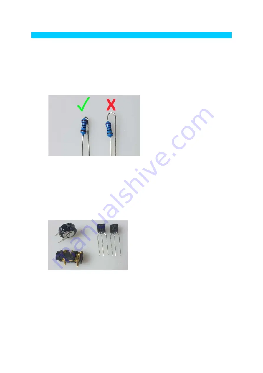
These resistors need to be soldered vertically. The leads need to be
formed as shown below. Bend the leads of each resistor as shown
and solder in to the correct postion, making sure the component
body is as close to the board as possible.
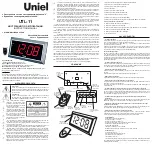
7.2 Q6, Q7 (MPSA42)
GPS (SMD Jack Connector)
C8 (0.22F)
To solder the GPS / RFT connector: First wet one pad on the PCB
with solder. Then place the connector in position and re-touch the
pad with the soldering iron. This will anchor the component and
then you can solder the remaining pads.
Ensure the arrows on C8 are aligned with the corresponding arrows
on the PCB


