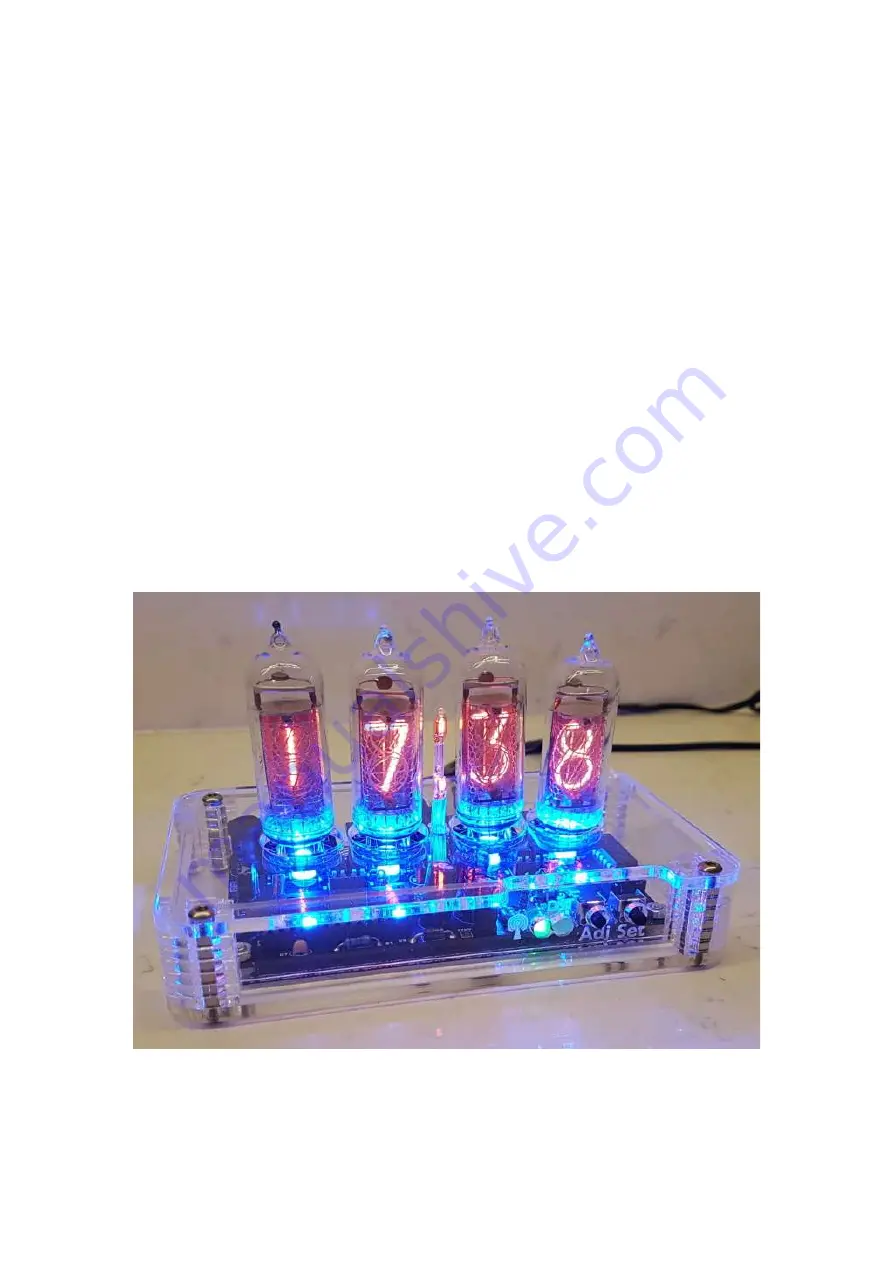
Nixie Tube Clock ‘Nixie QTC-Four’
Issue 1 (1 December 2019)
www.pvelectronics.co.uk
- 1 -
Assembly Instructions
And
User Guide
Nixie Clock Type
‘Nixie QTC-Four’
For Parts Bag Serial
Numbers from 100 onwards
Page 1: ...Nixie Tube Clock Nixie QTC Four Issue 1 1 December 2019 www pvelectronics co uk 1 Assembly Instructions And User Guide Nixie Clock Type Nixie QTC Four For Parts Bag Serial Numbers from 100 onwards ...
Page 2: ...Nixie Tube Clock Nixie QTC Four Issue 1 1 December 2019 www pvelectronics co uk 2 REVISION HISTORY Issue Number Date Reason for Issue Issue 1 01 December 2019 New document ...
Page 3: ...leading zero blanking Double dot colon neon lamps Seconds can be reset to zero to precisely the set time Programmable night mode blanked or dimmed display to save tubes or prevent sleep disturbance Front Indicator LEDs dim at night to prevent sleep disturbance Separate modes for colon neons during night mode Standard fading or crossfading with scrollback display modes Slot Machine Cathode poisonin...
Page 4: ...de range of solder in tubes as detailed in the table below There are detailed and specific instructions for mounting each type of tube in sections 5 1 to 5 6 of this manual Tube types Section IN 14 5 1 IN 8 2 ZM1177 5 2 Z570M Z5700M Z573M Z5730M Z574M Z5740M GN 9A B570M TAF1317A TAU7030 F9080B F9080BA TAF1093A ZM1080 ZM1082 ZM1134 ZM1135 ZM1136 ZM1136A ZM1136L ZM1136R ZM1138A ZM1138L ZM1138R 5 3 G...
Page 5: ...ges generated by this circuit can give a potentially LETHAL ELECTRIC SHOCK DISCLAIMER This product is supplied as a kit of parts intended only for suitably qualified electronic engineers who are suitably qualified and experienced in electronics assembly and are familiar with safe procedures for working with high voltages The supplier his agents or associates accept no liability for any damage inju...
Page 6: ...hot air gun will be needed to shrink the heat shrink tubing over the neon lamp wires 2 2 Materials you will need Solder lead tin solder is highly recommended USE LEAD TIN SOLDER Lead free solder as now required to be used in commercial products in Europe has a much higher melting point and can be very hard to work with Desoldering wick braid can be useful if you accidentally create solder bridges ...
Page 7: ... Q2 Q5 EL817 Optocoupler Q6 Q7 MPSA42 Diodes D1 D3 1N5819 D4 1N4148 D5 UF4004 DST 5mm Yellow LED SYNC 5mm Green LED RGB1 RGB4 APA106 RGB LED Integrated Circuits IC1 LM2576 SMD 5V voltage regulator IC2 PIC16F1936 8 bit microcontroller IC3 K155ID1 Nixie Driver Miscellaneous L1 L2 100uH inductor AM PM 4mm wire ended neon lamp SET ADJ Miniature horizontal push button IC2 Socket 28 Way narrow IC socket...
Page 8: ...ptocoupler 4 Diodes 1N5819 3 UF4004 fast recovery diode 1 1N4148 1 5mm Green LED 1 5mm Yellow LED 1 APA106 RGB LED 4 Integrated Circuits LM25876 SMD 1 PIC16F1936 8 bit microcontroller 1 K155ID1 1 Miscellaneous 100uH inductor 2 4mm wire ended neon lamp 2 Miniature horizontal push button 2 28 way narrow IC Socket for IC2 1 16 way narrow IC Socket for IC2 1 8 Way IC Socket 2 2 1mm PCB power socket 1 ...
Page 9: ...ad Therefore we recommend that the resistors be identified with a multimeter Please note the fuse will look like the picture below It can easily be confused for a capacitor It is a self resetting fuse The 10pF and 33pF capacitors will be marked 10 and 33 respectively The 100nF capacitors will be marked 104 Q1 IRFD220 is in a very similar package to Q2 Q5 EL817 You can tell the difference in additi...
Page 10: ...CT DEVELOPMENT AND IMPROVEMENTS YOUR PCB MAY NOT LOOK EXACTLY LIKE THE ONE PICTURED 4 1 Low Voltage Power components J1 FUSE D1 D3 1N5819 D4 1N4148 IC1 LM2576 L1 100uH Inductor C1 C2 220uF Start by installing IC1 Wet one end pad with solder as shown below Now place the part IC2 over the soldered pad Ensure the part is ...
Page 11: ...ll aligned over the other pads and then re heat the solder to anchor the part to the PCB Now you can solder the remaining 4 pads of the IC Do not solder the tab of the PCB Now solder the four diodes taking care that the band on the diode matches the band marked on the PCB as shown below ...
Page 12: ...n below Plug in the power supply and then test using a DC voltmeter Touch the black probe on the GND test point and the red probe on the 5V test point The voltage should measure between 5 4 and 5 8 Volts If not disconnect power and check your work Do not proceed with the assembly until the error is corrected Once the test is completed disconnect the power IF YOU CHOOSE TO PROCEED BEYOND THIS POINT...
Page 13: ...the notched end of the IC socket is at the end shown However if you find you soldered it with the wrong orientation do not try to remove it It is perfectly fine with the notch at the wrong end just be sure to place the IC in the socket with the IC s notch in the correct position Also the MOSFET needs to be placed with the two joined pins at the position shown below C3 and C4 are polarised the long...
Page 14: ...ator Test Refer to the warnings on page 5 Power up the PCB and using the GND and 170 test points measure the high voltage generated using a voltmeter on DC setting It should be between 164 and 176 Volts If this is in order disconnect the power supply If you do not get this voltage do not proceed Refer to the troubleshooting section IF YOU CHOOSE TO PROCEED BEYOND THIS POINT WITHOUT GETTING THE COR...
Page 15: ... 6 R11 R12 R13 R14 2 7 KΩ 4 7 R7 R8 R9 R10 1 KΩ 4 8 Sockets for Q2 Q5 Note Earlier versions of the kit may not have the sockets its perfectly safe to solder Q2 to Q5 directly to the PCB Once you have soldered the 2 sockets insert Q2 to Q5 noting the orientation of the dot on each part ...
Page 16: ... notch on one end of the socket with the marking on the PCB If you find you soldered it in the wrong orientation don t try to remove it See the troubleshooting section Now you can insert IC3 into the socket noting the orientation as shown below 4 10 NX1 NX4 6X2 way male pin header This is how the PCB should now look ...
Page 17: ...Nixie Tube Clock Nixie QTC Four Issue 1 1 December 2019 www pvelectronics co uk 17 ...
Page 18: ...s a white coating where it enters the glass Then remove the wires each side of the anode To facilitate easy insertion of the flying leads into the small holes it helps enormously to trim the flying leads with a pair of scissors as shown below Start at the anode lead then working around the tube cut each sucessive lead approx 2mm shorter than the previous one This will allow you to feed each lead i...
Page 19: ...sert and solder in the tube Pay attention that the tube sits squarely on the PCB Then solder on the connector Keep the tube 5mm 0 2 from the PCB Failure to keep this separation will invalidate any tube warranty claim The tube cell is now complete Repeat for the other 3 tubes Then move on to step 6 ...
Page 20: ...ber 12 wires into 12 holes To facilitate easy insertion of the flying leads into the small holes it helps enormously to trim the flying leads with a pair of scissors as shown below Start at one of the leads at the back of the tube Then working around the tube cut each sucessive lead approx 2mm shorter than the previous one This will allow you to feed each lead in in turn Now you can insert and sol...
Page 21: ...Nixie Tube Clock Nixie QTC Four Issue 1 1 December 2019 www pvelectronics co uk 21 Then solder on the connector The tube cell is now complete Repeat for the other 3 tubes Then move on to step 6 ...
Page 22: ...cessary to clip off two of the Z570M and equivalent tube leads Clip off the two leads as shown below This is how the tube will look after removing the leads To facilitate easy insertion of the flying leads into the PCB holes it helps enormously to trim the remaining flying leads with a pair of scissors as shown below Start at one of the leads at the back of the tube ...
Page 23: ...ious one This will allow you to feed each lead in in turn Now you can insert and solder in the tube There are 11 leads on the trimmed tube and 12 pads on the PCB One of the pads on the PCB is unconnected DO NOT INSERT A LEAD INTO THIS HOLE Insert from the side of the PCB with no markings Pay attention that the tube sits squarely on the PCB Then solder on the connector ...
Page 24: ...Nixie Tube Clock Nixie QTC Four Issue 1 1 December 2019 www pvelectronics co uk 24 The tube cell is now complete Repeat for the other 3 tubes Then move on to step 6 ...
Page 25: ...of the flying leads into the small holes it helps enormously to trim the flying leads with a pair of scissors Start at one of the leads at the back of the tube Then working around the tube cut each sucessive lead approx 2mm shorter than the previous one This will allow you to feed each lead in in turn Now you can insert and solder in the tube Insert the 11 leads into the 11 holes with pads as show...
Page 26: ...ics co uk 26 Pay attention that the tube sits squarely on the PCB Ensure the tube is facing perfectly forwards before soldering you may need to twist it a little Then solder on the connector The tube cell is now complete Repeat for the other 3 tubes Then move on to step 6 ...
Page 27: ...rtion of the flying leads into the small holes it helps enormously to trim the flying leads with a pair of scissors Start at one of the leads at the back of the tube Then working around the tube cut each sucessive lead approx 2mm shorter than the previous one This will allow you to feed each lead in in turn Now you can insert and solder in the tube Insert the 11 leads into the 11 holes with pads a...
Page 28: ...ics co uk 28 Pay attention that the tube sits squarely on the PCB Ensure the tube is facing perfectly forwards before soldering you may need to twist it a little Then solder on the connector The tube cell is now complete Repeat for the other 3 tubes Then move on to step 6 ...
Page 29: ... as for XN11 and XN12 below XN11 and XN12 These tubes have 11 leads and a gap at the very back of the tube To facilitate easy insertion of the flying leads into the small holes it helps enormously to trim the flying leads with a pair of scissors Start at one of the leads at the back of the tube Then working around the tube cut each sucessive lead approx 2mm shorter than the previous one This will ...
Page 30: ...ics co uk 30 Pay attention that the tube sits squarely on the PCB Ensure the tube is facing perfectly forwards before soldering you may need to twist it a little Then solder on the connector The tube cell is now complete Repeat for the other 3 tubes Then move on to step 6 ...
Page 31: ...epeat Please note this is a count UP not a count DOWN If you contact us with a support issue at this stage please be clear about the count up If you refer to a count down it will be very confusing and slow down your support query If you do not get this count up or have missing or overlapping digits stop and check your work Try swapping tubes around to see if the problem is with the tube or the loc...
Page 32: ...istor as shown and solder in to the correct postion making sure the component body is as close to the board as possible 7 2 Q6 Q7 MPSA42 GPS SMD Jack Connector C8 0 22F To solder the GPS RFT connector First wet one pad on the PCB with solder Then place the connector in position and re touch the pad with the soldering iron This will anchor the component and then you can solder the remaining pads En...
Page 33: ...C 5mm Green LED DST 5mm Yellow LED SET ADJ Push button switches First bend the leads of the LEDs as shown below paying attention to the longer lead being on the left hand side Then solder in place with the body of the LED just touching the PCB Then place and solder the 2 push button switches ...
Page 34: ...eon should be taller than the PM neon Use lengths of insulation and insert a tube into the clock to estimate the best height of each neon for your final case design Our suggestion is 35mm for the taller AM insulation and 25mm for the shorter PM insulation Slip the insulation over the neon lamp leads and with a hot air gun shrink the tubing Finally solder the neons in place on the PCB with the tall...
Page 35: ...Nixie Tube Clock Nixie QTC Four Issue 1 1 December 2019 www pvelectronics co uk 35 7 5 RGB1 RGB4 APA106 RGB LED To install the RGB LEDs first note the 2 longer of the 4 leads and insert as shown below ...
Page 36: ...electronics co uk 36 7 6 DEKA 3 way right angle Dekatron connection header Soldering this part will allow you to connect the clock to our dual dekatron driver Dekaduo It provides power ground and a sync pulse so the DekaDuo does not even need its own power supply ...
Page 37: ...ue holding the button a further 2 seconds until the clock displays in this format 00 XX In configuration mode the hours digits display the current parameter being adjusted and the minutes digits display the current value stored against the parameter For each parameter and referring to the table below scroll through the range of possible values by pressing the ADJ button When the desired value has ...
Page 38: ...s 1 9 600 bps default 10 Time Calibration Factor 0 99 each unit adjusts by 0 2s per day 11 Time Calibration Polarity 0 Make clock slower 1 Make clock faster 12 Slots Mode 0 Slots disabled 1 Slots every minute 2 Slots every 10 minutes default 3 Slots every hour 4 Slots at midnight 13 Display Mode 0 Standard change of digits 1 Cross fading digits with scrollback effect default 14 Seconds display eac...
Page 39: ...rammed night blanking the blanking may be overridden to see the time by briefly pressing the SET button Tubes will remain lit for the period defined in parameter 15 Rapid DST Adjustment Press ADJ briefly to toggle between DST and standard time The yellow LED indicator shows whether DST mode is active or not Note that GPS time data does not contain DST information so the DST status will need to be ...
Page 40: ...tible WiFi Device which obtains time from a NTP time server through your home internet 9 1 Configuring for GPS or WiFi Synchronisation Default baud rate is 9 600 bps Set parameter 9 to value 0 for 4 800 bps Set parameters 16 and 17 for the hours and minutes your time zone is offset from UTC Time This is usually only whole hours Set parameter 18 to identify whether the offset is minus 0 or positive...
Page 41: ... uk 41 10 CONNECTING OUR DEKATRON DRIVER The clock can be connected by just 3 wires to our DekaDuo Dual OG4 Dekatron Driver Please refer to the separate DekaDuo instructions for full details on how to do this Control of the Dekatron in night modes is possible using parameter 19 ...
Page 42: ...e 5 6V IC2 Socket Pin 2 Should be 0 14V IC2 Socket Pin 13 Should be 0V IC2 Socket Pin 20 Should be 5 2V If pin 2 is not to spec check the feedback resistors R2 and R3 are correct and correctly soldered If pin 20 is not to spec check why the PIC is not getting power via D3 Orientation Then put IC2 back into its socket and test the voltages again 5V test Point Should be 5 6V HV test point Should be ...
Page 43: ...Nixie Tube Clock Nixie QTC Four Issue 1 1 December 2019 www pvelectronics co uk 43 12 CIRCUIT DIAGRAM ...
Page 44: ...Nixie Tube Clock Nixie QTC Four Issue 1 1 December 2019 www pvelectronics co uk 44 ...