


USER GUIDE:
Ionic® Purification System
Purigen Biosystems
FOR RESEARCH USE ONLY.
Not for use in diagnostic procedures.
45
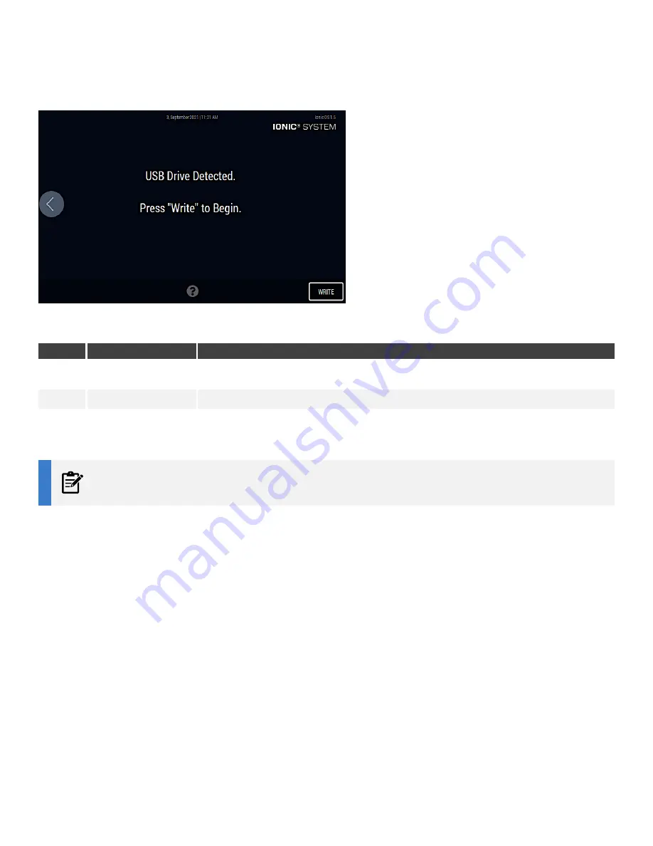
FIGURE 40:
Save System Logs Screen -
Step 2
TABLE 19:
Save System Logs screen
Call Out
Screen Component
Definition
1
Write button
A button to copy the system log to the USB drive inserted in the USB slot in the font of the instrument. The system
log file is copied to the root directory of the USB drive
2
Help icon
Loads the Help screen
4.
A status bar is displayed on the touchscreen.
NOTE
The status bar may seem inactive for larger log files. Wait for the system log to be saved to the USB flash drive.
5.
After the system log file is saved to the USB flash drive, press the button on the left side to return to the
Maintenance & Service
screen.