New Outlook Welder-MIG/MAG Series
3
INSTALLATION INSTRUCTION
If the connecting cable is too long, it will have a great influence on the arcing performance as well as the stability of the welding performance.
Therefore,please use the recommended length.If you want to reduce the voltage drop, please use a cable with a larger cross section.
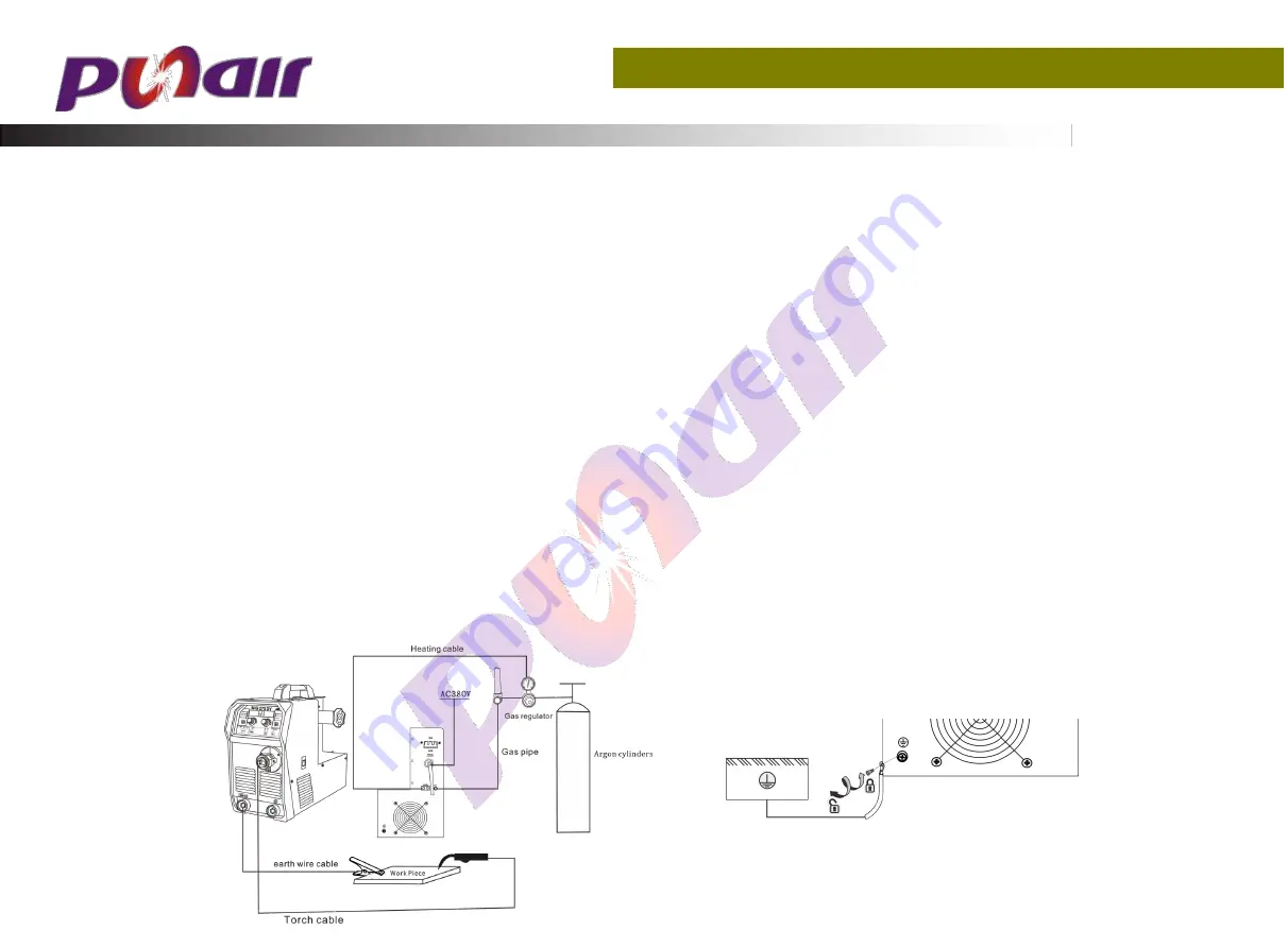
1)The gas cylinder equipped with the carbon dioxide gas pressure reducing flow meter is closely connected with the gas inlet of the carbon dioxide inlet at
the back of the machine.
2)Plug the ground wire quick plug into the corresponding quick socket on the front panel.
3)The wire spool equipped with the welding wire is mounted on the frame shaft of the wire feeder, and the hole position of the wire wire plate is aligned
with the fixing bolt on the frame shaft.
4)Depending on the diameter of the wire used, choose a different wire feed slot.
5)Loosen the nut of the pressure roller, feed the welding wire into the wire feeder groove through the wire guide tube, adjust the pressure wire to press
the welding wire to ensure that the welding wire does not slide, but the pressure should not be too large, to prevent the wire from being deformed and
affecting the wire feeding.
6)The wire spool should be rotated clockwise to release the wire. In order to prevent the wire from loosening, the new wire disk head is often placed in the
fixing hole on the side of the wire disk. In order to prevent the bent wire from being stuck during normal use, cut off this part of the wire.
7)The torch is inserted into the output socket of the front panel and tightened, and the wire is inserted into the gun body. Ground the cables with section
area no less than 6mm2 to the housing,the way is connecting screw in the back of the power source to ground device;.


