Pulsar SG108 Quick Start Manual Download Page 2


1.2. Block diagram. 


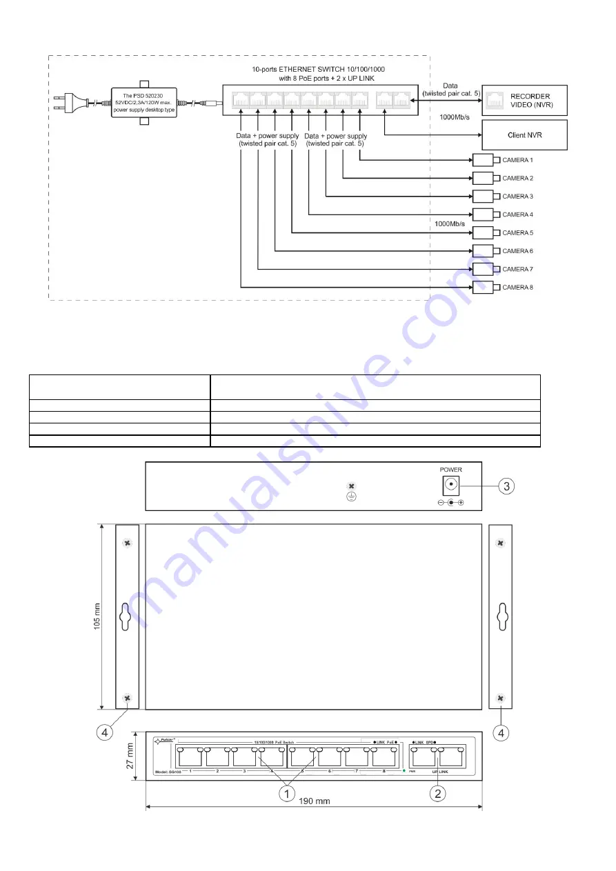
Fig. 1. Block diagram. 


1.3.  Description of components and connectors. 

 
Table 1. (see Fig. 2) 

Element no. 

(Fig

. 2) 

Description


[1] 

8 x PoE port (1

÷8)  

[2] 

2 x UP LINK port  

[3] 

Power Socket of the DC 

[4] 

Additional assembly elements 


Fig. 2. The view switch'a. 

Summary of Contents for SG108

Page 1: ...m the production date Example of use 1 Technical description 1 1 General description SG108 is a 10 ports PoE switch designed to supply IP cameras operating in IEEE 802 3af at standard Automatic detection of any devices powered in the PoE PoE standard is enabled at the 1 8 ports of the switch The UP LINK ports is used for connection of another network device via RJ45 connector The LEDs at the front...

Page 2: ...1 Block diagram 1 3 Description of components and connectors Table 1 see Fig 2 Element no Fig 2 Description 1 8 x PoE port 1 8 2 2 x UP LINK port 3 Power Socket of the DC 4 Additional assembly elements Fig 2 The view switch a ...

Page 3: ...ve humidity RH 90 maximum without condensation and temperature from 10 C to 40 C Ensure the free flow of air around the unit The PSU shall work in a vertical position that guarantees sufficient convectional air flow through ventilating holes of the enclosure The switch load balance should be done before installation The given value of 30 W per port is the maximum value referring to a single output...

Page 4: ...4 Connection schemes ...

Page 5: ... no connection ON the device is connected 10 100 1000 Mb s Blinking data transmission OPTICAL INDICATION AT THE UP LINK PORTS GREEN LED LIGHT OFF no connection the device is connected 10 Mb s or 100 Mb s ON the device is connected 1000 Mb s YELLOW LED LIGHT LINK The connection status of LAN devices 10 100 1000 Mb s and data transmission OFF no data transmission ON the device is connected 10 100 10...

Reviews: