background image

www.pulsar.pl   


PSBEN5024C/LCD 


24 

4. Battery-assisted operation. 


4.1. Running the PSU from the battery. 


The PSU has been equipped with two buttons on the pcb board which enable running or disconnecting the 

PSU during battery-assisted operation. 


Running the PSU from the battery: press the START button on the main board and hold for 1s. 


Disconnecting the PSU from the battery: press the STOP button on the main board and hold for 5s. 


4.2. Deep discharge battery protection UVP. 

The PSU is equipped with the disconnection system and the discharged battery indication. If the voltage at 

the  battery  terminals  drops  below  20V±0.2V  during  battery-assisted  operation,  the  battery  will  be  disconnected 
after appr.15s.  

Switching off/on the function of the battery protection: 
Press the ‘SET’ button from the level of the LCD desktop and then choose:  

”PSU -> Battery protection: YES/NO”

 (see chapter 3.4.2, table 7). 


Caution. 
Deactivating of the UVP function is not recommended since a deep discharge of the battery limits its 
capability of storing energy, lowers its capacity and shortens its durability. 


4.3 Dynamic battery test. 

The PSU runs a battery test every  10 minutes. It is done by a momentary switching into a battery-assisted 

operation. A failure is indicated when voltage drops below 24V. The battery test facility can be switched off. 

Deactivating/activating the test:  
- enter the PSU settings from the level of the LCD desktop by pressing the ‘SET’ button. Then choose:  

”PSU -> Battery protection: YES/NO”

 (see chapter 3.4.2, table 7) or 

             - from the pcb level: during mains-powered PSU operation press the STOP button on the main board and 
hold it for 3 seconds.  
           The  device  will  confirm  the  activation/deactivation  of  the  test  (see  tab.8  [6,  7])  and  show  an  appropriate 
message on the display: 

”TEST ON/ TEST OFF”


Deactivating/activating  the  test  is  stored  in  the  memory  even  after  unplugging  the  device  from 
mains.  The  battery  failure  indication  at  the  APS  FLT  output  is  automatically  switched  off.  The 
battery protection system against deep discharged remains on, though.  


4.4. Battery charging time. 


The  PSU  has  a  battery  circuit  charged  with  direct  current.  The  current  selection  is  done  via 

I

BAT

  jumpers. 

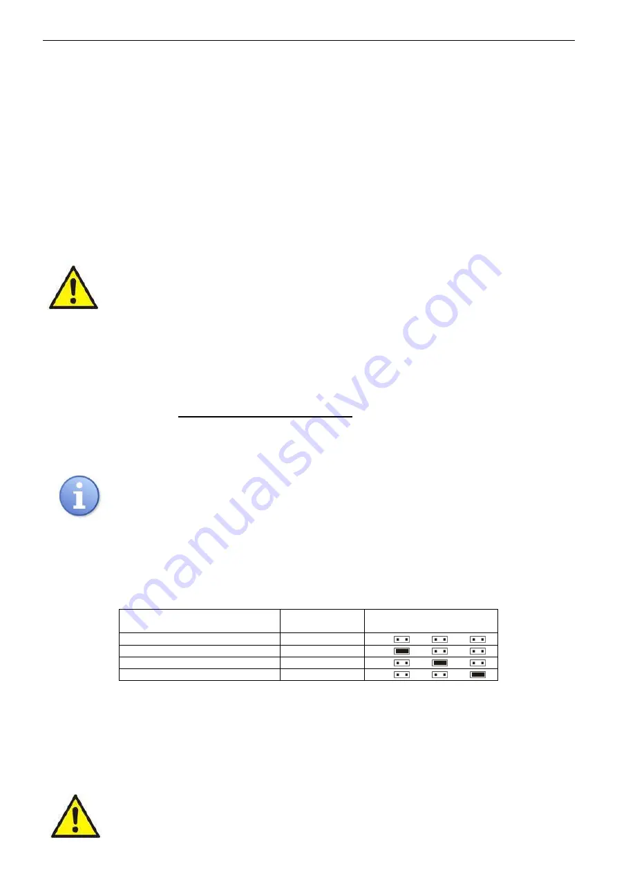
The  table  below  shows  how  long  it  takes  to  charge  a  (fully  discharged)  battery  up  to  min.  80%  of  its  nominal 
capacity.  


Table 9. Battery charging time. 

2x17Ah

 battery charging time  

up to capacity of 0,8*C 

Charging 

current [A] 

Configuration of 

I

BAT 

jumper 

5h6m 

J1= 

, J2= 

, J3= 


7h 

2,2 

J1= 

, J2= 

  J3= 


10h12m 

1,5 

J1= 

, J2= 

  J3= 


25h30m 

0,6 

J1= 

, J2= 

  J3= 


4.5 Operation without a battery. 


In case of an expected PSU operation without an attached battery, make a necessary configuration setting 

from the level of the LCD desktop (see chapter 3.4.2, table 7).


”Settings -> PSU -> Battery present: YES/NO”


In this mode the automation system allows adjustments of PSU’s output voltage without indicating a failure 

connected with working of the battery. 


CAUTION. During operation without battery assistance the PSU does not perform any parameter 
control that monitors its proper operation. Therefore, this mode ought to be chosen thoughtfully. 

Summary of Contents for PSBEN 5024C

Page 1: ...PSBEN 5024C LCD v 1 0 PSBEN 27 6V 5A 2x17Ah EN LCD Buffer switched mode power supply unit EN Edition 2nd 14th Sep 2012 Supersedes the 1st 25th April 2012 edition...

Page 2: ...17 Setting the communication address 18 3 4 3 Desktop 18 Setting the language of messages 19 Setting the date 19 Setting the time 20 Setting the highlighting 20 Setting the contrast 21 3 5 ACOUSTIC IN...

Page 3: ...S 29 7 2 INSTALLATION PROCEDURE 29 8 OPERATION AND USE 30 8 1 OVER VOLTAGE PROTECTION OVP AT THE PSU OUTPUT 30 8 2 OVERLOAD OF THE PSU 30 8 3 SHORT CIRCUIT AT THE PSU OUTPUT 30 8 4 BATTERY REPLACEMENT...

Page 4: ...f access password protected PSU s operation history failure history real time clock battery backed optical indication of PSU overload OVL acoustic indication of failure adjustable times indicating AC...

Page 5: ...2 6A 3A battery charge Total current of the receivers battery 5 6A max In case of power decay a battery back up is activated immediately The PSU is housed in a metal enclosure colour RAL 9005 black w...

Page 6: ...on on indication off Caption jumper on jumper off 6 VADJ potentiometer DC voltage adjustment 7 BUZZER acoustic indicator 8 FBAT fuse in the battery circuit 9 Connectors AC AC power input BAT DC power...

Page 7: ...ement no Description 1 Insolation transformer 2 PSU board tab 1 fig 2 3 TAMPER micro switch contacts of tamper resistance NC 4 FMAIN fuse in the supply circuit 230 V AC 5 L N 230V AC power connector P...

Page 8: ...atus indication 3 1 Control panel The PSU is equipped with a panel with buttons and an LCD display which enables reading all available parameters of the device The buttons are for selecting and approv...

Page 9: ...lay The main screen of the LCD display shows basic electrical parameters and informs about the current PSU state Fig 5 The main screen Table 4 Description of the symbols on the main screen Screen fiel...

Page 10: ...status during operation Highlighting of an element informs about an active state and reflects the status of LEDs on the pcb of the PSU see table 1 12 Fig 7 Screen parameters of the PSU Table 5 Descrip...

Page 11: ...analysis of the values shown on the chart the time range of the chart screen can be adjusted in the bottom axis Here are the available ranges 8h 24h 2days week weekly In order to change the displayed...

Page 12: ...erates 3 levels of access to configuration which limit the possibility of changing the PSU s settings from the level of the LCD desktop They are protected with separate passwords Keypad password locks...

Page 13: ...ear with or choose the right level of the password confirm your choice with the SET button with or enter the first digit confirm your choice with the SET button with or enter the second digit confirm...

Page 14: ...swords have been lost there is a procedure that will allow reassigning the passwords Please do as follows a unplug the PSU from the AC network and the battery for at least 10 seconds b press the STOP...

Page 15: ...to the PSU NO battery not connected to the PSU see chapter 4 6 Battery test YES battery test on NO battery test off see chapter 4 3 Battery protection YES battery protection function disconnection on...

Page 16: ...onfirm your choice with the SET button Setting the battery test with or choose the Battery test menu press the SET button you will see the prompt at the end of the line with or set YES or NO YES batte...

Page 17: ...nction disconnection on NO battery protection function disconnection off confirm your choice with the SET button Setting the EPS output lag with or choose the EPS output lag menu press the SET button...

Page 18: ...mputer confirm your choice with the SET button 3 4 3 Desktop The facility is only available after entering the correct user s or installer s password The Desktop menu enables setting the current date...

Page 19: ...you will see the prompt at the end of the line with or choose the language of messages confirm your choice with the SET button Setting the date with or choose the Date menu press the SET button the pr...

Page 20: ...ection with or set the minutes press the SET button the prompt will move to the second section with or set the seconds approve the settings with the SET button Setting the highlighting Intensity of th...

Page 21: ...t to the constant option with or change the setting into 60 s press the SET button the prompt will move to the end of the line with or set the demanded screen brightness approve your choice with the S...

Page 22: ...se In case of a power failure the PSU will switch the output into the open state after a period of time determined by the EPS output lag facility see 3 4 2 table 7 APS FLT output indicating battery fa...

Page 23: ...IN technical input has been implemented with galvanic isolation between the PSU s systems and the devices attached Fig 16 Electrical diagram of the EXT IN input The electrical diagram below shows the...

Page 24: ...ET button Then choose PSU Battery protection YES NO see chapter 3 4 2 table 7 or from the pcb level during mains powered PSU operation press the STOP button on the main board and hold it for 3 seconds...

Page 25: ...age of wireless communication is lack of additional cords and fast development or modification of the network s structure Fig 19 WI FI communication with the use of the WI FI INTW interface 5 2 Commun...

Page 26: ...USB TTL INTU needs to be used This interface allows direct connection between the computer and the PSU and it is recognisable by the operating system as a virtual COM port Fig 22 USB TTL communicatio...

Page 27: ...put voltage adjustment range 24V 29 V Ripple voltage 160 mV p p max Current consumption by the PSU systems during batter assisted operation I 26mA I 17 mA highlighting of the LCD desktop is off Batter...

Page 28: ...cables can be led Convectional cooling Table 12 Operation safety Protection class PN EN 60950 1 2007 I first Protection grade PN EN 60529 2002 U IP20 Electrical strength of insulation between input ne...

Page 29: ...3 7 and guarantees indication in case of any attempts of detaching the device from the mounting surface Fig 24 Fixing a tamper grip 2 Connect the power cables 230Vac to L N terminals of the PSU Connec...

Page 30: ...tie and appropriate message on the PSU front panel 8 2 Overload of the PSU The PSU has been equipped with a LED OVL overload indicator light on the pcb It informs about the output overload status If t...

Page 31: ...high output voltage Output voltage 29 4V F07 ON 2 flashes ON PSU FLT Too high battery voltage Battery voltage 28V F08 ON 3 flashes ON PSU FLT Battery charging circuit failure Too low output voltage of...

Page 32: ...eriod mentioned in item 6 may be prolonged if there are no technical possibilities to carry out the repairs or if the equipment has been conditionally accepted due to the breaking warranty terms by th...

Reviews: