NO.
NO.
NO.
NO.
PART
PART
PART
PART NO.
NO.
NO.
NO.
DESCRIPTION
DESCRIPTION
DESCRIPTION
DESCRIPTION
Q'TY
Q'TY
Q'TY
Q'TY
REMARK
REMARK
REMARK
REMARK
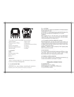
1
DJ190F-12100-BE
CRANKSHAFT ASSEMBLY
1
2
GB276-89-6202
BALL RADIAL BEARING 6202
2
3
DJ188F-12004-A
BALANCING SHAFT
1
4
DJ190F-12300-C
PISTON RING SET
1
5
DJ188F-12003-A
PISTON PIN CIR-CLIP
2
6
DJ190F-12001-D
PISTON
1
7
DJ188F-12002-A
PISTON PIN
1
8
DJ190F-12200-AE
CONNECTING ROD ASSEMBLY
1
32
Summary of Contents for PG7500B
Page 1: ...7500 7500B 1 866 591 8921 ...