background image


10 


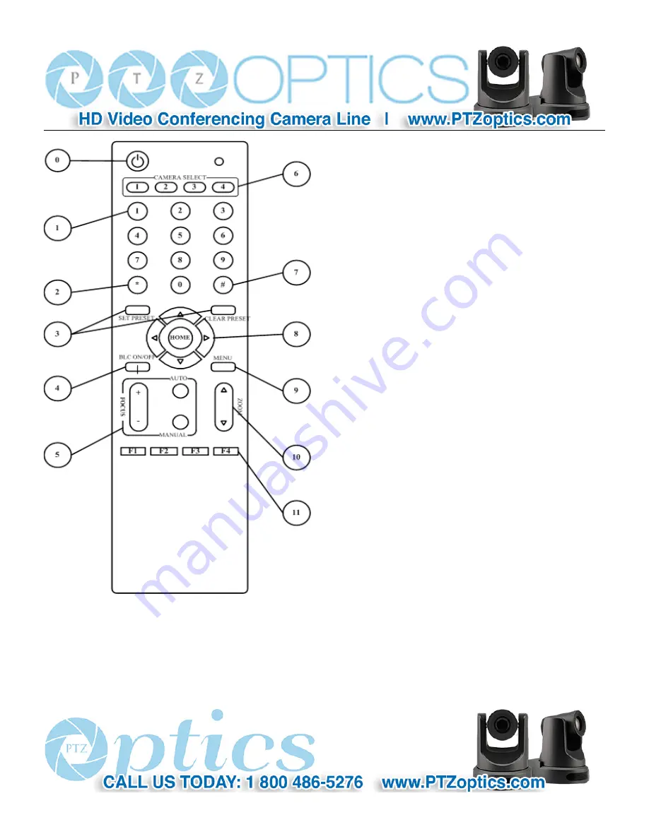
IR Remote Controller Explanation 

0. Standby Button 

Press  this  button  to  enter  standby  mode.  Press  it  again  to 

enter normal mode.   

(Note:  Power  consumption  in  standby  mode  is 

approximately half of the normal mode) 

1. Position Buttons 

To set preset or call preset 

2. * Button 

3. Set/Clear Preset Buttons 

Set preset: 

Store a preset position


[SET  PRESET]  +  Numeric  button  (0-9):  Setting  a 

corresponding numeric key preset position 

Clear preset: 

Erase a preset position 

[CLEAR PRESET] + Numeric button (0-9) 

Or:  [*]+[#]+[CLEAR  PRESET]:  Erase  all  the  preset 

individually 

4. BLC (Backlight Compensation) Button 

BLC  ON/OFF: 

Press  this  button  to  enable  the  backlight 

compensation.  Press  it  again  to  disable  the  backlight 

compensation.(NOTE: Effective   

only in auto exposure mode)


Note: If a light behind the subject, the subject will   

become  dark.  In  this  case,  press  the  backlight  ON  /  OFF  button.  To  cancel  this  function,  press  the  backlight  ON  /  OFF 

button. 

5. Focus Buttons 

Used for focus adjustment. 

Summary of Contents for 20X-USB

Page 1: ...PTZ Optics 20X USB User Manual V1 0 English...

Page 2: ...camera to rain or moisture n Don t remove the cover Otherwise you may get an electric shock In case of abnormal operation contact the authorized engineer n Never operating under unspecified temperatur...

Page 3: ...Explanation 12 8 Use IR Remote Controller 14 9 RS 232 Interface 17 10 Serial Communication Control 19 11 Menu Setting 33 12 Maintains and Trouble Shooting 38 Supplied Accessories When you unpack chec...

Page 4: ...of installation Do not grasp the camera head when carrying the camera Don t turn camera head by hand Doing so may result in mechanical damage Don t apply in corrosive liquid gas or solid environment...

Page 5: ...rt Step1 Please check connections are correct before starting Step2 Setting switches Set both of the switch1 and switch2 to OFF That is Normal Working Mode SW 1 SW 2 Modes 1 OFF OFF Normal Working Mod...

Page 6: ...lamp light Step5 Pan Tilt will rotate to the maximum position of top right after the camera started then it return to the center the process of initialization is finished Note If the position preset...

Page 7: ...th high quality maximum output frame rate reach 30 frames per second 4 High SNR of CMOS sensor combined with 2D and 3D noise reduction algorithm effectively reduce the noise even under low illuminatio...

Page 8: ...NTSC 1 30 is 30 Digital Zoom 16x I frame interval Customizable greater than the maximum frame rate Minimal Illumination 0 5 Lux F1 8 AGC ON Video format PAL NTSC Shutter 1 25s 1 10000s Web frame Main...

Page 9: ...7 100 s Power Connector JEITA type DC IN 12V Tilt Speed Range 1 7 69 9 s Input Voltage 12V DC 10 8 13 0V DC Ceiling Installation Support Current Consumption 2 0A Max Number of Preset 245 Operating Te...

Page 10: ...1 Audio LINE IN Interface 7 RS232 IN jack 2 Audio LINE OUT Interface 8 RS232 OUT jack 3 CVBS Interface 9 Network 4 Dip switches 10 USB3 0 5 System select switch 11 DC 12V jack 6 RS485 jack 12 Power sw...

Page 11: ...corresponding numeric key preset position Clear preset Erase a preset position CLEAR PRESET Numeric button 0 9 Or CLEAR PRESET Erase all the preset individually 4 BLC Backlight Compensation Button BLC...

Page 12: ...Press the button corresponding to the camera you want to operate with the remote controller 7 Button 8 Pan Tilt Control Buttons Press arrow buttons to perform panning and tilting Press HOME button to...

Page 13: ...required 2 When a button combination is required do it in sequence For example F1 means press first and then press and press F1 at last 1 Pan Tilt Control Move up Press Move down Press Move left Pres...

Page 14: ...ON OFF Press this button to enable the backlight compensation Press it again to disable the backlight compensation Note Backlight is only effective in full auto exposure mode 5 Presets Set Clear 1 To...

Page 15: ...ored preset positions and settings Note No action is executed if a relative preset position is not stored 7 Camera Selection Press the button corresponding to the camera you want to operate 8 Camera I...

Page 16: ...XD 4 GND 4 DTR 5 RXD 5 GND 6 GND 6 DSR 7 IR OUT 7 RTS 8 NC 8 CTS 9 RI Camera Mini DIN 1 DTR 1 DTR 2 DSR 2 DSR 3 TXD 3 TXD 4 GND 4 GND 5 RXD 5 RXD 6 GND 6 GND 7 IR OUT 7 NC 8 NC 8 NC VISCA Network Conf...

Page 17: ...ect to a VISCA controller with RS232C serial interface RS232 Communication Control The camera can be controlled via RS232 the parameters of RS232C are as follows Baud rate 2400 4800 9600 bit s Start b...

Page 18: ...1 bit Data bit 8 bits Stop bit 1bit Parity bit none Pan Tilt will rotate to the maximum position of top right after the camera started then it return to the center the process of initialization is fin...

Page 19: ...command format is different or when a command with illegal command parameters is accepted Command Buffer Full z0 60 03 FF Indicates that two sockets are already being used executing two commands and t...

Page 20: ...ele Standard 8x 01 04 07 02 FF Wide Standard 8x 01 04 07 03 FF Tele Variable 8x 01 04 07 2p FF p 0 low 7 high Wide Variable 8x 01 04 07 3p FF Direct 8x 01 04 47 0p 0q 0r 0s FF pqrs Zoom Position CAM_F...

Page 21: ...4 39 03 FF Manual Control mode Shutter priority 8x 01 04 39 0A FF Shutter Priority Automatic Exposure mode Iris priority 8x 01 04 39 0B FF Iris Priority Automatic Exposure mode Bright 8x 01 04 39 0D F...

Page 22: ...3 0p FF p Flicker Settings 0 Off 1 50Hz 2 60Hz CAM_DHotPixel 8x 01 04 56 0p FF p Dynamic Hot Pixel Setting 0 0ff level 1 to 6 CAM_ApertureMode sharpness Auto 8x 01 04 05 02 FF Sharpness Auto Manual 8x...

Page 23: ...WW 02 02 FF Stop 8x 01 06 01 VV WW 03 03 FF AbsolutePosition 8x 01 06 02 VV WW 0Y 0Y 0Y 0Y 0Z 0Z 0Z 0Z FF RelativePosition 8x 01 06 03 VV WW 0Y 0Y 0Y 0Y 0Z 0Z 0Z 0Z FF Home 8x 01 06 04 FF Reset 8x 01...

Page 24: ...ommand Command packed Inquiry Packet Comments CAM_PowerInq 8x 09 04 00 FF y0 50 02 FF On y0 50 03 FF Off Standby y0 50 04 FF Internal power ciruit error CAM_ZoomPosInq 8x 09 04 47 FF y0 50 0p 0q 0r 0s...

Page 25: ...3 FF Manual Noise 3D CAM_Nosise2DLevel 8x 09 04 53 FF y0 50 0p FF Noise Reduction 2D p 0 to 5 CAM_Noise3DLevel 8x 09 04 54 FF y0 50 0p FF Noise Reduction 3D p 0 to 8 CAM_FlickerModeIn q 8x 09 04 55 FF...

Page 26: ...A Version vw Camera model 01 C Type 02 M Type 03 S Type VideoSystemInq 8x 09 06 23 FF y0 50 00 FF 1920x1080i60 y0 50 01 FF 1920x1080p30 y0 50 02 FF 1280x720p60 y0 50 04 FF NTSC y0 50 05 FF NTSC y0 50...

Page 27: ...y0 50 01 FF High y0 50 02 FF Normal y0 50 03 FF Low CAM_BrightnessInq 8x 09 04 A1 FF y0 50 00 00 0p 0q FF pq Brightness Position CAM_ContrastInq 8x 09 04 A2 FF y0 50 00 00 0p 0q FF pq Contrast Positi...

Page 28: ...Exposure Comp vv Shutter Position ww Iris Position xx Bright Position z Exposure Comp Position CAM_OtherBlockInq 8x 09 7E 7E 02 FF y0 50 0p 0q 00 0r 00 00 00 00 00 00 00 00 00 FF p bit0 Power 1 On 0 O...

Page 29: ...Preset 0xFF Address 0x00 0x03 0x00 Preset ID SUM Clear Preset 0xFF Address 0x00 0x05 0x00 Preset ID SUM Call Preset 0xFF Address 0x00 0x07 0x00 Preset ID SUM Auto Focus 0xFF Address 0x00 0x2B 0x00 0x0...

Page 30: ...t 0xA0 Address 0x00 0x03 0x00 Preset ID 0xAF XOR Clear Preset 0xA0 Address 0x00 0x05 0x00 Preset ID 0xAF XOR Call Preset 0xA0 Address 0x00 0x07 0x00 Preset ID 0xAF XOR Auto Focus 0xA0 Address 0x00 0x2...

Page 31: ...pCompMode Exposure compensation mode Optional items On Off Effective only in Auto mode ExpComp Exposure compensation value Optional items 7 7 Effective only in ExpComp Mode item to On Gain Limit Maxim...

Page 32: ...main menu and press home button COLOR menu appears as shown in the following figure WB Mode White balance mode Optional items Auto Indoor Outdoor One Push ok Manual RG Red gain Optional items 0 255 Ef...

Page 33: ...ems On Off Flip V Image Flip Vertical Optional items On Off B W Mode Image color Optional items On Off Gamma Optional items Default 0 45 0 5 0 56 0 63 5 P T Z SpeedByZoom The depth of field scale swit...

Page 34: ...ptional items AUTO VISCA PELCO D PELCO P V_Address Protocol address To be decided according to the agreement AUTO VISCA protocol Optional items 1 7 P_D_Address PELCO D protocol Optional items 0 254 P_...

Page 35: ...ress home button RESTORE DEFAULT menu appears as shown in the following figure Restore Confirm restore factory settings Optional items Yes No Note Press HOME button to confirm All parameter restore de...

Page 36: ...0 or more advanced version 2 Equipment Installation 1 Connect internet camera to your internet or to your PC directly via internet cable 2 Turn on DC12V power 3 The orange light of internet port lit o...

Page 37: ...ade_En exe in small CD in package shown as below Run upgrade_En exe UPGRADE v1 8 by CD Rom click Search The software will show the current LAN camera s IP address subnet mask number network gateway nu...

Page 38: ...37 Click config then go to below...

Page 39: ...en camera IP must be 192 168 1 xx the first second third number must keep the same NOTE IP camera default IP address 192 168 100 88 user admin password admin 2 Visit Access IP Camera 2 1 Input http 19...

Page 40: ...39 2 2 Input login name and password click confirm then pop up below window language select button on the left bottom...

Page 41: ...Setup IPC accessed controlled by dynamic DNS 2 dynamic DNS available Dyndns org 3322 org 1 1 Router Port Mapping Take TP LINK router for example enter Router Home Page interface page select Transit co...

Page 42: ...xample setup host computer name youdomain f3322 org camera port number 554 Access link should be http youdomain 3322 org 554 NOTE If camera port default as 80 then unnecessary to input port number use...

Page 43: ...42 1 2 Input URL address rtsp ip port number 1 Main stream rtsp ip port number 2 sub stream When RTSP port number default value is 554 then can be omitted as rtsp ip 1 or rtsp ip 2...

Page 44: ...same as video resolution the bigger the resolution is the bigger the playing area is Double click viewing window will show full screen double click again will return to initialized size Status bar in...

Page 45: ...ction button to realize PTZ speed up or speed down 3 Zoom In Zoom out for zooming in or zooming out Focus In Focus Out Focusing on distant objects or Focusing on close objects 4 Set Call When PTZ turn...

Page 46: ...45 1 Media 1 1 Video Setup please click Video 1 Video format Support 50HZ PAL and 60HZ NTSC and Dial priority three formats 2 Video Coding Support baseline and mainprofile format 3 Resolution...

Page 47: ...nsmitted normally the video effect will be worse 5 Maximum frame rate User can specify the size of the frame rate generally the frame rate greater the image more smooth Frame rate is smaller the more...

Page 48: ...the right shows the corresponding numerical Default 50 3 Contrast Contrast0 100 slider control on the right shows the corresponding numerical Default 57 4 Sharpness Sharpness0 100 slider control on t...

Page 49: ...alize image around the mirror Default not tick 8 Button Adjusting the parameters press apply button to save press cancel button to cancel the adjustment of the parameters press default button obtain t...

Page 50: ...cel parameter 4 System Setting please click System 1 Work Mode Work Mode RTSP 2 Reboot Click the Reboot button system restart 3 User and password The user can modify the password letters and Numbers o...

Page 51: ...k device the device can run multiple web applications each network program using network port to transmit data so data transmission to be carried out between the port and port Port setting is to set u...

Page 52: ...Support TCP protocol default port 5678 5 Apply Cancel Modify network parameters then press Apply button to modify network parameters press Cancel button to cancel network parameters 6 Device Informati...

Page 53: ...e by one the camera IP address will be shown on screen Method 2 connect camera to PC with ethernet cable use upgrade_En exe to search for IP address l Please enter the IP address username password to...

Page 54: ...53 Method 2 Open upgrade_En exe change IP and click Set...

Page 55: ...d to restart the camera 2 methods to restart as below Method 1 Turn off and turn on manually to restart camera Method 2 On web page find System and click Apply when under remote controlling environmen...

Page 56: ...n Command Packet Comments Zoom Stop 81 01 04 07 00 FF Tele Standard 81 01 04 07 02 FF Wide Standard 81 01 04 07 03 FF Tele Variable 81 01 04 07 2P FF P 0 low speed 7 high speed Wide Variable 81 01 04...

Page 57: ...Camera IP This camera IP address action including up down left right ptzstop pan speed 1 low speed 24 high speed tilt speed 1 low speed 20 high speed 2 2 Zoom control URLformat as below http Camera IP...

Page 58: ...More descriptions Camera IP This camera IP address action including posset poscall position number 0 89 100 254 USB Control Connect USB cable from camera to computer must with USB3 0 port Install the...

Page 59: ...onditions otherwise image will be flickering l No operating close to powerful electromagnetic radiation such as TV or radio transmitters etc Troubleshooting Image l No image 1 Check whether the power...

Page 60: ...able is connected correctly Copyright Notice All contents of this manual whose copyright belongs to our Company Cannot be cloned copied or translated without the permission of the company Product spec...

Reviews: