background image

Chapter  3: Getting to Know the 8515

Audio Indicators

Psion Teklogix 8515 Vehicle-Mount Computer User Manual

27

Security Level

Security levels can be set to limit user access to 8515 settings. In addition, applications can 
be restricted to prevent inadvertent changes.

External Power

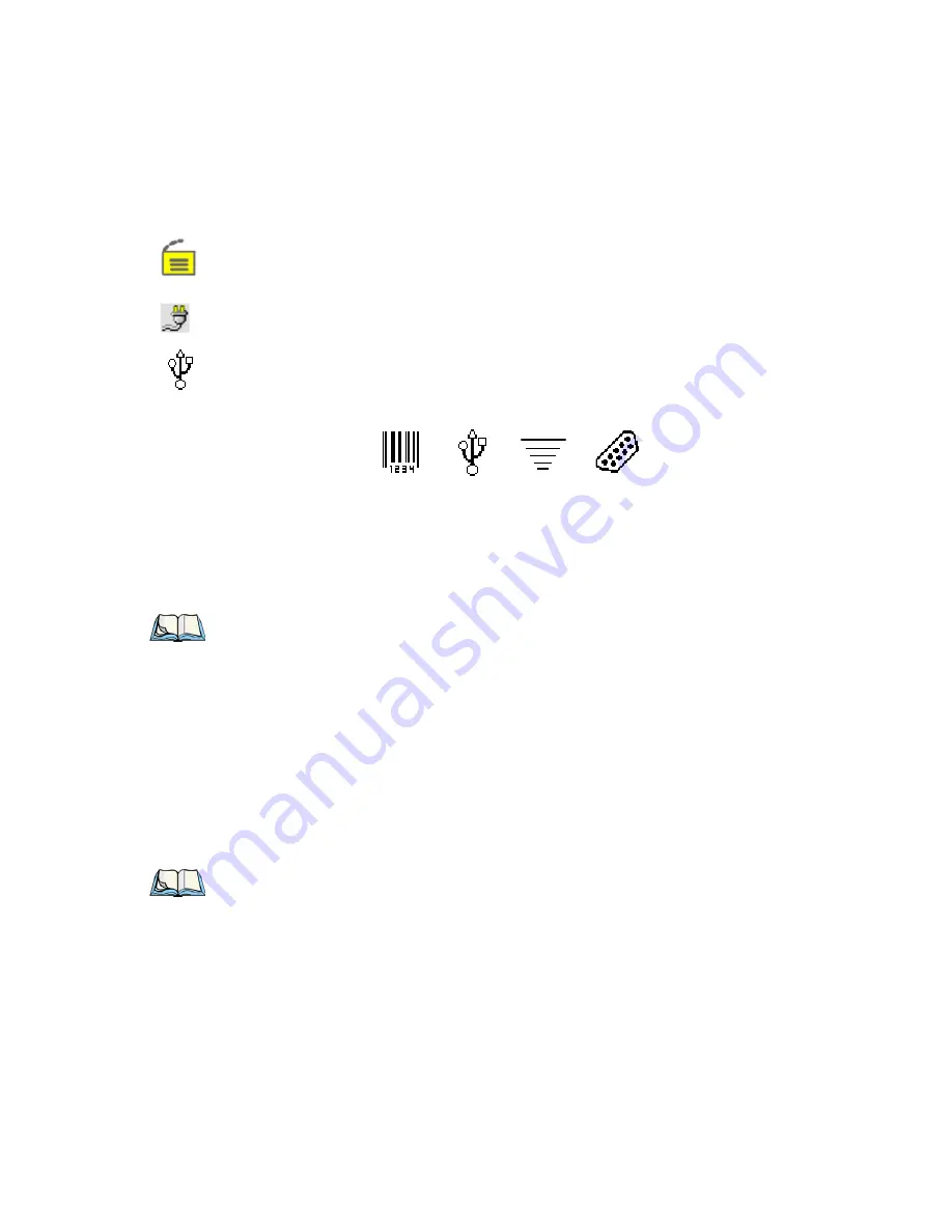
This is the external power icon displayed in the taskbar.

External Devices

When a peripheral is attached to the USB or serial ports and activated, an associated icon 
appears in the taskbar.

3.6.3   Audio Indicators

The 8515 beeper provides a variety of sounds and can be configured to emit a sound when a 
key is pressed, a keyboard character is rejected, scan input is accepted or rejected or an oper-
ator’s entry does not match in a match field. 

3.7

  Scanning

Decoded scanners must be configured by scanning special configuration bar codes. In these 
cases, the scanner manufacturer provides programming manuals for configuration purposes. 
The 8515 supports a variety of one dimensional (1D) scanners and two dimensional (2D) 
laser and imager scanners. “Scanning Techniques” outlines the mechanics of a successful 
scan. In addition, “Troubleshooting” on page 28 provides some helpful suggestions should 
the scan fail.

3.7.1   Scanning Techniques

Hold the scanner at an angle. Do not hold it perpendicular to the bar code.

Do 

not

 hold the scanner directly over the bar code. In this position, light can reflect back 

into the scanner’s exit window and prevent a successful decode.

Scanner

RFID

Serial Device

USB Device

Note:

Refer to “Scanner Settings” on page 87 for details about the Volume & Sound 

Properties dialog box.

Note:

External scanners can be connected to the 8515 serial or USB device port.

Summary of Contents for Vehicle-Mount Computer 8515

Page 1: ...8515 Vehicle Mount Computer User Manual January 28 2010 P N 8100132 B ISO 9001 Certified Quality Management System ...

Page 2: ... up to date In ad dition changes are periodically added to the information herein these changes will be incor porated into new editions of the publication Psion Teklogix Inc reserves the right to make improvements and or changes in the prod uct s and or the program s described in this document without notice and shall not be re sponsible for any damages including but not limited to consequential d...

Page 3: ...repairs To locate your local support services please go to www psionteklogix com service and support htm To access further information on current and discontinued products please go to https teknet psionteklogix com and log in or tap on Not Registered depending on whether you have previously registered for Teknet A section of archived product information is available online This Product and its ac...

Page 4: ...rket in EU member states after July 1 2006 Although there is no legal requirement to mark RoHS compliant products Psion Teklogix Inc indicates its compliance with the directive as follows The RoHS logo located either on the back of the product or underneath the battery in the battery compartment or on a related accessory such as the charger or docking station signi fies that the product is RoHS co...

Page 5: ... Conventions 3 1 3 About the 8515 Vehicle Mount Computer 4 Chapter 2 Basic Checkout 2 1 Features of the 8515 7 2 2 Preparing the 8515 for Operation 8 2 3 8515 Safety Instructions 8 2 4 Important Operating Instructions 9 2 5 Switching the 8515 On and Off 9 2 6 Calibrating the Touchscreen 10 2 7 Data Transfer Between the 8515 and a PC 11 2 7 1 Using Microsoft ActiveSync 11 2 7 2 Using Windows Vista ...

Page 6: ...r Indicator LED 25 3 6 2 Onscreen Indicators 25 3 6 3 Audio Indicators 27 3 7 Scanning 27 3 7 1 Scanning Techniques 27 3 7 2 Scan LED Indicators 28 3 7 3 Troubleshooting 28 3 7 4 Operating One Dimensional 1D Laser Scanners 28 3 7 5 Operating PDF Laser Scanners 28 3 8 Monitoring the Network Connection 29 3 9 General Maintenance 29 3 9 1 Ports 29 3 9 2 Caring for the Touchscreen 29 3 9 3 Cleaning th...

Page 7: ...on 5 1 Remote Desktop Connection 51 5 2 Pocket PC Compatibility 51 5 3 The Control Panel 51 5 4 Control Panel Icons 52 5 5 Control Panel Applications Basic Setup 56 5 5 1 App Launch Keys 56 5 5 2 Certificates 58 5 5 3 Display Properties 58 5 5 3 1 Background 58 5 5 3 2 Appearance 59 5 5 3 3 Backlight 59 5 5 4 Input Panel 60 5 5 5 Keyboard Properties 62 5 5 5 1 Key Repeat 63 5 5 5 2 Backlight 63 5 ...

Page 8: ...81 5 6 1 2 Services 82 5 6 1 3 Set PIN 83 5 6 2 The Servers Tab 83 5 6 3 Outgoing Tab 84 5 6 4 Active Connections Tab 85 5 6 5 Properties Tab 86 5 7 IPv6 Support 86 5 8 Scanner Settings 87 5 8 1 Decoded Scanners 87 5 8 2 Scanner Settings Options Tab 87 5 8 2 1 Double Click 88 5 8 2 2 Display 88 5 8 3 Translations Tab 89 5 8 3 1 Case Rules 91 5 8 4 Ports Tab 91 5 8 4 1 Serial Port COM 1 92 5 9 SNMP...

Page 9: ...file Information 104 5 11 1 2 Add Files 105 5 11 1 3 View Selections 105 5 11 1 4 Performing the Backup 106 5 11 2 Restoring a Profile 106 5 12 TweakIT Settings 107 5 12 1 Advanced 107 5 12 1 1 Advanced Interface and Network 107 5 12 1 2 Advanced Services Settings 108 5 12 1 3 Advanced Intermediate Driver 109 5 12 1 4 Radio Features 110 5 12 2 User 111 5 12 2 1 Internet Explorer Settings 111 5 12 ...

Page 10: ... Power to the 8515 127 6 6 3 1 Installing the Power Pre regulator 128 Chapter 7 Specifications 7 1 8515 Vehicle Mount Computer Specifications 133 7 2 Colour Display 134 7 3 Keyboard 135 7 4 External Power 135 7 5 Internal Lithium Polymer Battery 135 7 6 Radio Specifications 135 7 7 External Bar Code Scanners 136 Appendix A Port Pinouts A 1 Serial Port Interface Pinout DB 9 male A 1 A 2 Enhanced US...

Page 11: ...Contents Psion Teklogix 8515 Vehicle Mount Computer User Manual vii C 1 1 Launching the Application C 1 C 1 2 Installation Complete Dialog Box C 3 Index I ...

Page 12: ......

Page 13: ... YOUR AGREEMENT TO THIS EULA OR RATIFICATION OF ANY PREVIOUS CONSENT GRANT OF SOFTWARE LICENSE This EULA grants you the following license You may use the SOFTWARE only on the DEVICE NOT FAULT TOLERANT THE SOFTWARE IS NOT FAULT TOLER ANT PSION TEKLOGIX INC HAS INDEPENDENTLY DETERMINED HOW TO USE THE SOFTWARE IN THE DEVICE AND MS HAS RELIED UPON PSION TEKLOGIX INC TO CONDUCT SUFFICIENT TESTING TO DE...

Page 14: ...e the SOFTWARE except and only to the extent that such activity is expressly permitted by applicable law notwithstanding this limitation SOFTWARE TRANSFER ALLOWED BUT WITH RESTRICTIONS You may permanently transfer rights under this EULA only as part of a permanent sale or transfer of the Device and only if the recipient agrees to this EULA If the SOFTWARE is an upgrade any transfer must also inclu...

Page 15: ... the Software 2 DESCRIPTION OF REQUIREMENTS RESTRICTIONS RIGHTS AND LIMITATIONS a Copy The right and license granted to you shall be limited to installation and use of the Software up to but not exceeding the number of copies you have licensed However you may make a copy of the Software for backup or archival purposes You shall not remove any copyright notice or proprietary notices labels or marks...

Page 16: ...ld lead to death personal injury or severe physical or environ mental damage High Risk Activities We specifically disclaim any express or implied warranty of fitness for High Risk Activities 4 DISCLAIMER OF WARRANTY We do not warrant uninterrupted or error free operation of the Software nor do we warrant that the Software will meet your requirements THE SOFTWARE IS PROVIDED AS IS WITHOUT ANY WARRA...

Page 17: ...Any copies of the Software you made are subject to the restrictions of this Agreement WE DISCLAIM ALL WARRANTIES AND INDEMNITIES EXPRESS IMPLIED OR STATUTORY FOR PATENT OR COPYRIGHT INFRINGEMENT 7 CONFIDENTIALITY You agree not to use or disclose any proprietary information provided by us except for the purposes of this Agreement You agree not to reproduce any of the copyrighted materials unless ex...

Page 18: ...ater time either in relation to that default or any subsequent one No modifications of this Agreement shall be effective unless in writing and approved by us You acknowledge that you have read this Agreement understand it and that it is the com plete agreement between you and Psion Teklogix with respect to the subject matter hereof and supersedes all prior agreements oral or written ...

Page 19: ...ogix 8515 Vehicle Mount Computer User Manual xv APPROVALS AND SAFETY SUMMARY CE Marking xvii R TTE Directive 1999 5 EC xvii FCC Information to Users xviii Emissions Information for Canada xx Warnings to Users xx ...

Page 20: ...xvi Psion Teklogix 8515 Vehicle Mount Computer User Manual ...

Page 21: ...les de la Directiva 1995 5 CE de la UE Equipos de Terminales de Radio y Telecomu nicaciones Declaración disponible en www psion teklogix com Este equipamento cumpre os requisitos essenciais da Directiva 1999 5 CE do Parlamento Europeu e do Conselho Directiva RTT Declaração disponível no endereço www psion teklogix com Ο εξοπλισμός αυτός πληροί τις βασικές απαιτήσεις της κοινοτικής οδηγίας EU R TTE...

Page 22: ...o indoor use They may be used outdoors on private property only with prior authorization from the French Ministry of Defense FCC Information to Users Federal Communication Commission Interference Statement This equipment has been tested and found to comply with the limits for a Class B digital device pursuant to Part 15 of the FCC Rules These limits are designed to provide reason able protection a...

Page 23: ...16 2 Psion Teklogix Case Integrated Antenna P N 1070545 3 Mobile Mark Model IMAG5 2400 The use of any other configuration requires its own FCC approval Some equipment in hospitals and aircraft are not shielded from radio fre quency energy Do not use the 8515 onboard aircraft or in hospitals without first obtaining permission Do not use near pacemakers The product may affect the operation of some m...

Page 24: ...r il est alors soumis à licence Warnings to Users RF Exposure To satisfy FCC RF exposure requirements for vehicle mount transmitting devices a separa tion distance of 20 centimeters should be maintained between the antenna of this device and persons during device operation To ensure compliance operations at closer than this dis tance is not recommended Do Not Remove Covers or Open Enclosures To av...

Page 25: ...stepped on tripped over or otherwise subjected to damage or stress An extension cord should not be used unless absolutely necessary Use of an improper extension cord could result in fire or electric shock To reduce risk of electric shock unplug the vehicle mount computer from the DC source before attempting any maintenance or cleaning Warning Physically disconnect the 8515 from the vehicle battery...

Page 26: ......

Page 27: ...Psion Teklogix 8515 Vehicle Mount Computer User Manual 1 INTRODUCTION 1 1 1 About This Manual 3 1 2 Text Conventions 4 1 3 About the 8515 Vehicle Mount Computer 4 ...

Page 28: ...2 Psion Teklogix 8515 Vehicle Mount Computer User Manual ...

Page 29: ...apter also outlines the basics of moving around a Windows Embedded CE 5 0 window selecting and opening icons and files and working with a dialog box Chapter 5 Configuration provides a description of the Windows Embedded CE 5 0 Control Panel and how to use it to configure the 8515 along with the scanners attached to the unit Chapter 6 Peripheral Devices 8515 Installations describes the peripherals ...

Page 30: ...cations with a focus on real time wireless data transactions A wide range of data input capabilities are supported through a variety of imager RFID and bar code scanner options Figure 1 1 8515 with Qwerty Keyboard Note Notes highlight additional helpful information Important These statements provide particularly important instructions or additional information that is critical to the operation of ...

Page 31: ...s 8 2 4 Important Operating Instructions 9 2 5 Switching the 8515 On and Off 9 2 6 Calibrating the Touchscreen 10 2 7 Data Transfer Between the 8515 and a PC 11 2 8 Summit Client Utility SCU for 802 11b g Radio 12 2 8 1 Assigning the IP Address 12 2 8 2 Name Servers Tab 13 2 8 3 Using the SCU to Connect to the WLAN 14 2 9 Resetting the 8515 Vehicle Mount Computer 16 ...

Page 32: ...6 Psion Teklogix 8515 Vehicle Mount Computer User Manual ...

Page 33: ...mputer User Manual 7 2 1 Features of the 8515 Figure 2 1 Front of the 8515 Vehicle Mount Computer Figure 2 2 8515 Ports Power LED Function Keys Function Keys Macro Keys Beeper Antenna UART DB 9 Port USB Device Port Enhanced USB Host Ports Speaker Mic Jack for external devices console ...

Page 34: ...d could result in fire or electric shock If an extension cord must be used make sure The plug pins on the extension cord are the same number size and shape as those on the adaptor The extension cord is properly wired and in good electrical condition and that the wire size is larger than 16 AWG When the unit is connected to the battery or AC adaptor the mains power cord shall comply with National s...

Page 35: ...the 8515 is turned on from suspend state operation resumes within a few seconds Warning IT IS CRITICAL that this information be reviewed and that any guidelines applicable to your 8515 be strictly followed Note If the backup battery temperature is less than 10 C and a brown out occurs the display backlight will switch off in order to maintain computer operations The backlight will switch back on w...

Page 36: ...se the Stylus icon to display the Stylus Properties window Choose the Calibration tab and then tap on the Recalibrate button Follow the directions on the calibration screen to calibrate the screen Important If the word BLUE is displayed in uppercase in the taskbar at the bottom of the screen this key is locked on the 8515 will not switch off Press the BLUE key again to unlock it then press BLUE EN...

Page 37: ... again if needed and so on 2 7 1 Using Microsoft ActiveSync To install ActiveSync follow the step by step instructions provided with the program s setup wizard Refer to the following website for details http www microsoft com windowsmobile activesync activesync45 mspx 2 7 2 Using Windows Vista If you have Windows Vista your 8515 data transfers do not require ActiveSync To transfer data between you...

Page 38: ...h a wireless LAN effectively and securely 2 8 1 Assigning the IP Address Before launching the SCU follow the steps below to determine how the IP address will be obtained either via DHCP or by specifying an address 1 Tap on Start Settings Network and Dial up Connections 2 Choose the Summit WLAN Adapter icon to open the 802 11 Wireless LAN Set tings window in the sample screen below this is labelled...

Page 39: ...s tap on Specify an IP address and type the preferred address as well as the IP Subnet Mask and Default Gateway addresses in the appropriate fields Tap OK to save your information 2 8 2 Name Servers Tab In the IP Information tab tap on the Configure button Tap on the Name Servers tab Note Choosing the Renew button forces the 8515 to renew or find a new IP address This is useful if for example you ...

Page 40: ...s is 2 8 3 Using the SCU to Connect to the WLAN This section provides a quick set of steps to create a profile referred to as a config Detailed information about each of the SCU tabs Main Config Status Diags and Global Set tings is provided in Appendix B SCU for 802 11b g Radio To launch the SCU so that your computer can connect to a wireless LAN 1 Tap on Start Programs Summit SCU Figure 2 3 SCU M...

Page 41: ...ID setting 2 8 3 2 EAP Type Tap on the EAP type drop down menu and choose the appropriate type of authenti cation LEAP EAP FAST PEAP MSCHAP and PEAP GTC Next tap on the Credentials button and type credentials for IEEE 802 1X EAP types 2 8 3 3 Encryption Tap on the Encryption drop down menu and choose the appropriate type of encryp tion Manual WEP Auto WEP WPA PSK WPA TKIP WAP2 PSK WAP2 AES CCKM TK...

Page 42: ...s being used derive dynamic encryption keys If DHCP is being used by the network obtain an IP address If the radio is not connecting properly Tap on the Status tab The Status dialog box lists the IP and MAC addresses and indicates the current state of the radio the signal strength channel and so on You can go to the Diags tab for DHCP renewal ICMP Echo Requests Pings and diagnostics 2 9 Resetting ...

Page 43: ...enu Press and hold down the BLUE key the ENTER key and the SPACE key simulta neously for a minimum of six seconds After a cold reset the BooSt menu appears If you want to load the Windows Embedded CE 5 0 operating system type 1 If you want a clean start press that is SHIFT 1 All data and settings are lost Files and data stored in flash are preserved Once the OS loads any executables and cab files ...

Page 44: ......

Page 45: ... Keys 24 3 4 2 Macro Keys 24 3 4 3 The Keypad Backlight 25 3 5 The Display 25 3 6 8515 Indicators 25 3 6 1 Power Indicator LED 25 3 6 2 Onscreen Indicators 25 3 6 3 Audio Indicators 27 3 7 Scanning 27 3 7 1 Scanning Techniques 27 3 7 2 Scan LED Indicators 28 3 7 3 Troubleshooting 28 3 7 4 Operating One Dimensional 1D Laser Scanners 28 3 7 5 Operating PDF Laser Scanners 28 3 8 Monitoring the Networ...

Page 46: ...20 Psion Teklogix 8515 Vehicle Mount Computer User Manual ...

Page 47: ...d by authorized Psion Teklogix personnel 3 2 The Stylus The stylus is supplied with a holder with double sided adhesive tape so that it can be at tached wherever is most convenient for you 3 3 The Keyboard The 8515 provides a 58 key QWERTY or ABC alphanumeric keyboard layout Most of the keys on these keyboards operate much like a desktop computer If a key or key function is not consistent with the...

Page 48: ...r key will remain active until it is pressed a third time to unlock or turn it off Once a modifier key is unlocked pressed a third time the uppercase representation at the bottom of the screen is no longer displayed 3 3 2 The Keys The BLUE and ORANGE Keys The BLUE and ORANGE modifier keys provide access to additional symbols and keys These additional symbols and keys are colour coded in blue and o...

Page 49: ...ly entered key stroke The CTRL and ALT Key The CTRL and ALT keys modify the function of the next key pressed and are application dependent The TAB Key Typically the TAB key moves the cursor to the next field to the right or downward The ESC Key Generally this key is used as a keyboard shortcut to close the current menu dialog box or activity and return to the previous one The SPACE Key Pressing th...

Page 50: ...F20 These keys are labelled in orange in the top left corner of the function keys To access these keys press the ORANGE key followed by F1 to F10 To access function key F11 press the ORANGE key followed by F1 Press ORANGE F2 to access function key F12 etc Accessing Function Keys F21 to F30 These keys are labelled in blue in the top right corner of the function keys To access these keys press the B...

Page 51: ...ter visibility in low light conditions The backlight switches on when a key is pressed or the touchscreen is tapped The backlight intensity and the duration of time that the backlight will remain at full inten sity can be specified in the Display Properties dialog box in the Control Panel 3 6 8515 Indicators The 8515Vehicle Mount Computer uses onscreen messages and audio tones as indicators The co...

Page 52: ... key is displayed in the taskbar in lowercase characters for example pressing the BLUE key once displays blue key in the taskbar If a modifier key is pressed twice it is locked on and the onscreen indicator is displayed in uppercase letters in the taskbar for example pressing BLUE twice displays BLUE KEY in the taskbar 802 11 Radio Signal Quality Increasing radio signal quality is represented by l...

Page 53: ...7 Scanning Decoded scanners must be configured by scanning special configuration bar codes In these cases the scanner manufacturer provides programming manuals for configuration purposes The 8515 supports a variety of one dimensional 1D scanners and two dimensional 2D laser and imager scanners Scanning Techniques outlines the mechanics of a successful scan In addition Troubleshooting on page 28 pr...

Page 54: ...ing If the scanner is not working investigate the following Is the 8515 on Check that the scanner settings are correctly configured see Scanner Settings on page 87 Check the bar code to make sure it is not damaged Try scanning a different bar code to verify that the problem is not with the bar code Check that the bar code is within the proper range Does the computer display the warning without sca...

Page 55: ...dust caps on unused ports 3 9 2 Caring for the Touchscreen The top of the touchscreen is a thin flexible polyester plastic sheet with a conductive coating on the inside The polyester can be permanently damaged by harsh chemicals and is susceptible to abrasions and scratches Using sharp objects on the touchscreen can scratch or cut the plastic or crack the internal conductive coating If the touchsc...

Page 56: ...eaning the 8515 Use only mild detergent or soapy water to clean the computer Avoid abrasive cleaners solvents or strong chemicals for cleaning To clean ink marks from the keypad and touchscreen use isopropyl alcohol Important Do not immerse the unit in water Dampen a soft cloth with mild detergent to wipe the unit clean ...

Page 57: ...d 33 4 2 Working With Files Folders and Programs 34 4 3 The Startup Desktop 35 4 3 1 The Desktop Icons 36 4 3 2 The Taskbar 36 4 3 2 1 Using the Taskbar 37 4 3 2 2 Customizing the Taskbar 37 4 4 The Start Menu 38 4 4 1 The Desktop 38 4 4 2 Security Level 38 4 4 2 1 Changing a Password 39 4 4 2 2 Configuring Security 39 4 4 3 Programs 40 4 4 4 Shortcuts 41 4 4 5 Settings 43 4 4 6 Run 43 4 4 7 Shutd...

Page 58: ...32 Psion Teklogix 8515 Vehicle Mount Computer User Manual ...

Page 59: ...Touchscreen and Stylus v Each 8515 Vehicle Mount Computer is equipped with a stylus a pointing tool that looks like a pen that is used to select objects on the touchscreen To open a file launch an applet or open a folder Double tap the stylus on the appropriate icon To navigate through a dialog box for example display the information in a tab choose a radio button check a checkbox etc Tap the styl...

Page 60: ...in se quence Refer to Working With Files Folders and Programs below for additional details about keyboard navigation 4 2 Working With Files Folders and Programs Figure 4 1 Windows Explorer Screen Table 4 1 Keyboard Navigation Operation Key or Key Combination Switch between active applications ALT TAB Open task manager ALT ESC Move the cursor Arrow keys Open file folder or icon ENTER Exit Save ENTE...

Page 61: ...ng the keyboard Use the arrow keys to highlight the icon you want to open or launch Press ENTER 4 3 The Startup Desktop When the 8515 boots up the startup desktop shell is displayed Any applications stored in the Startup folder start up immediately Figure 4 2 Startup Screen Double tap on the icon to open a window or in the case of an application icon launch an application Note The startup folder i...

Page 62: ...Embedded CE 5 0 ver sion Keep in mind that your supervisor will need to set up access using the Internet Options and the Network and Dial up Connections icons in the Control Panel Microsoft WordPad Choosing this option launches Microsoft WordPad a trimmed version of the Microsoft Word application Remote Desktop Connection This option allows your 8515 to communicate with a remote desktop PC Remote ...

Page 63: ...e touchscreen To display a tooltip tap and hold the stylus on an icon To display the Control Panel dialog box associated with an icon double tap on the icon On the keyboard Press BLUE 0 zero to display the Start Menu Choose Shortcuts from the Start Menu and then press the RIGHT arrow key to display the sub menu Choose System Tray in the sub menu Use the arrow keys to highlight the icon in the task...

Page 64: ...the keyboard Press BLUE 0 zero to open the Start Menu Use the arrow keys to highlight a menu item and press ENTER or If the menu item has an underlined character type the underlined alpha character For example to display the Security dialog box type the letter s 4 4 1 The Desktop Choosing the Desktop option from the Start Menu displays the 8515 desktop 4 4 2 Security Level Choosing the Security op...

Page 65: ...123456 Tap on OK you can now access all menu items in the Start Menu along with the icons in the taskbar 4 4 2 1 Changing a Password To assign a password choose a security level and enter the existing password in the Password field Tap on the Set Password button A dialog box labelled Password Properties is displayed Type the new password in the Password text box In the Confirm Password text box re...

Page 66: ...ss Internet Explorer along with installed applications e g Microsoft WordPad Remote Desktop Connection and Windows Explorer ActiveSync ActiveSync is used to connect your 8515 to your PC Demo The Demo folder contains demo programs available on the 8515 Some demo programs such as Sound and Imager require hardware support not available Note It is recommended that you enable Allow Teklogix Security Le...

Page 67: ...ows Embedded CE 5 0 You can access the Internet Options icon through the Start Menu under Settings Control Panel or by double tapping on the desktop icon labelled My Device and then double tapping on the Control Panel icon Remote Desktop Connection Remote Desktop Connection is an 8515 application used to connect to a Windows Terminal Server so that you can run a session on the Server machine using...

Page 68: ... When System Tray is chosen you can access the taskbar icons using the arrow keys Press the LEFT and RIGHT arrow keys to highlight the icon in the taskbar about which you d like more information a tooltip is displayed as each taskbar icon is highlighted To display the Control Panel dialog box associated with the highlighted icon press ENTER Cycle Tasks When Cycle Tasks is selected and the Task Man...

Page 69: ...l Network and Dial Up Connections The Network and Dial up Connections window allows you to configure an 802 11 radio or execute an existing configuration Refer to Summit Client Utility SCU for 802 11b g Radio on page 12 for radio setup details Taskbar and Start Menu The Taskbar and Start Menu option displays a dialog box in which you can customize the taskbar selecting the icons that will be displ...

Page 70: ...he Suspend option suspends the 8515 immediately this is equivalent to turning the computer off Note This menu varies slightly depending on the security level chosen When the 8515 is set to User level the Shutdown option is replaced by Suspend A sub menu is not available At Teklogix security level an additional option is available in the sub menu Bootloader This option behaves like cold reset excep...

Page 71: ...tion resets the 8515 Any files not stored in permanent memory are lost However the registry settings are saved 4 5 Using a Dialog Box A dialog box like those in the sample screens in Figure 4 14 on page 45 appears when you need to make selections and enter further information Figure 4 14 Navigating Dialog Boxes Note A dialog box item that is displayed in grey text indicates that it is not currentl...

Page 72: ...lect or deselect an option To select or deselect a checkbox tap the stylus on the checkbox to select or deselect it Radio buttons These buttons allow you to choose from a number of options For example in the second sample screen in Figure 4 14 on page 45 you can choose to Obtain an IP address via DHCP or Specify an IP address Tap the stylus on the button to select or dese lect it Buttons This type...

Page 73: ...3 2 Appearance 59 5 5 3 3 Backlight 59 5 5 4 Input Panel 60 5 5 5 Keyboard Properties 62 5 5 5 1 Key Repeat 63 5 5 5 2 Backlight 63 5 5 5 3 One Shots 64 5 5 5 4 Macro Keys 65 5 5 5 5 Unicode Mapping 67 5 5 5 6 Scancode Remapping 68 5 5 5 7 Virtual Key Function and Macro 70 5 5 5 8 Lock Sequence 70 5 5 6 Manage Triggers 71 5 5 6 1 Trigger Mappings 72 5 5 6 2 Add and Edit Trigger Mapping 73 5 5 7 Po...

Page 74: ...erties Tab 86 5 7 IPv6 Support 86 5 8 Scanner Settings 87 5 8 1 Decoded Scanners 87 5 8 2 Scanner Settings Options Tab 87 5 8 2 1 Double Click 88 5 8 2 2 Display 88 5 8 3 Translations Tab 89 5 8 3 1 Case Rules 91 5 8 4 Ports Tab 91 5 8 4 1 Serial Port COM 1 92 5 9 SNMP Simple Network Management Protocol Setup 93 5 9 1 Contacts Tab 94 5 9 2 Communities Tab 95 5 9 2 1 Enable SNMP 95 5 9 2 2 Adding a...

Page 75: ... 10 3 Partition Management 101 5 10 3 1 Dismounting a Partition 101 5 10 3 2 Deleting a Partition 101 5 10 3 3 Formatting a Partition 101 5 10 3 4 Mounting a Partition 102 5 11 Total Recall 103 5 11 1 Creating a Backup Profile 103 5 11 1 1 Profile Information 104 5 11 1 2 Add Files 105 5 11 1 3 View Selections 105 5 11 1 4 Performing the Backup 106 5 11 2 Restoring a Profile 106 5 12 TweakIT Setti...

Page 76: ...50 Psion Teklogix 8515 Vehicle Mount Computer User Manual ...

Page 77: ...ket PC 2002 shell in an 8515 running Windows Embedded CE 5 0 The website listed below describes the APIs exposed through AYGShell and the application compatibility between Windows Powered Pocket PC 2002 based applications and Windows Embedded CE 5 0 based devices http msdn microsoft com library default asp url library en us dncenet html WINCENET_CEPCC_App asp 5 3 The Control Panel The Windows Embe...

Page 78: ...brief description of each Section 5 5 Control Panel Applications Basic Setup describes the basic configuration for these applications App Launch Keys Allows you to map keys to applications so that you can launch those applications from a single key press Bluetooth A short range wireless technology that enables data communication between devices It also provides the capability to use a Bluetooth en...

Page 79: ...let can also be used to adjust the backlight level Input Panel The 8515 is equipped with the framework for a Soft Input Panel SIP should you need to design your own SIP Internet Options Used to configure your Internet browser including options such as identifying the default and search page that the browser applies when connecting to the Internet setting the cache size specifying the Internet conn...

Page 80: ...in a safe place Refer to Security Level on page 38 for details PC Connection Enables direct connections to a desktop computer Selecting the Change Connection button allows you to change the type of direct connect to your PC Power Allows you to define if and when the unit will automatically switch to Suspend state It also allows you to turn power for the CF card slot on and off This dialog box also...

Page 81: ...some scanner parameters However the 8515 supports decoded scanners which must be configured by scanning special configuration bar codes see page 87 Total Recall This is a Psion Teklogix utility developed to maintain applications and setting over cold boots This utility is based on a backup and restore concept and is extended to incorpo rate powerful advanced features TweakIT Settings Allows you to...

Page 82: ...y press In the Control Panel choose the App Launch Keys icon To assign an application key Tap the Add button Press the key you want to use to launch an application If an unsupported key is pressed a message appears on this screen letting you know The cursor moves to the App field and a new screen is displayed where you can choose the application to which you want to assign the application key If y...

Page 83: ...lank If for example you want to assign an application launch key to launch the WordPad application you can leave this field blank If you want to assign an ap plication launch key that will open a specific document in the WordPad application you need to browse to and choose that document while the cursor is in the Data field Tap on OK If you need to Edit Remove or Add another App Launch Key you can...

Page 84: ...5 3 Certificates Menu For a detailed description about Certificate setup for both the server and client side devices 8515 refer to the following website www microsoft com windows2000 techinfo planning walkthroughs default asp Security Services 5 5 3 Display Properties In the Control Panel choose the Display icon Figure 5 4 Display Icon 5 5 3 1 Background The Background tab allows you to adjust the...

Page 85: ...e Tab This dialog box allows you to customize the display colour scheme and font size 5 5 3 3 Backlight The backlight is activated for a configurable amount of time when the 8515 is in use key press scanner trigger or data received from the host The Display Properties dialog box in the Control Panel allows you to specify the intensity of the backlight along with how long the display will maintain ...

Page 86: ... that the back light stays on at the configured intensity when a unit is not in use Dim For The value chosen from this dropdown menu determines the duration of time that the back light stays on at half the configured intensity dimmed backlight when a unit is not in use External Power Checkbox When you select the checkbox next to When using external power keep the backlight always ON the backlight ...

Page 87: ...ther than pressing a key you tap on letters numbers modifier keys etc on the 8515 screen To customize the appearance and behaviour of the soft keyboard Tap on the Input Panel icon in the Control Panel Soft Keyboard Input Panel Button Icon Important If the Input Panel button icon is not visible in the taskbar from the Start menu tap on Settings Taskbar and Start Menu Tap the checkbox next to Show I...

Page 88: ...s This icon displays the Keyboard Properties dialog box in which you can adjust the repeat rate of the keys the intensity of the keyboard backlight and the behaviour of the BLUE and ORANGE modifier keys This dialog box also allows you to define macro keys and remap the keyboard In the Control Panel choose the Keyboard icon Figure 5 10 Keyboard Icon Note You can also display this dialog box by doub...

Page 89: ...sition of the slider determines how long a key must be held down before it begins to autorepeat Repeat Rate The value assigned for the Repeat Rate parameter determines how quickly the key you press repeats and is measured in characters per second cps Sliding the bar to the left slows the repeat rate and sliding the bar to the right increases the repeat rate 5 5 5 2 Backlight In the Keyboard Proper...

Page 90: ... the right lightens the intensity Options ON For The value chosen from this dropdown menu determines the duration of time that the key board backlight stays on when a unit is not in use 5 5 5 3 One Shots In the Keyboard Properties dialog box open the One Shots tab Figure 5 13 One Shots Tab Note Tapping in the checkbox next to When using external power keep the backlight always ON forces the keypad...

Page 91: ...this option and you press the modifier key once it remains active only until the next key is pressed If you press the modifier key twice it is locked on remaining active until the modifier key is pressed a third time to turn it off 5 5 5 4 Macro Keys In the Keyboard Properties dialog box open the Macros tab Figure 5 14 Macros Tab Note Keep in mind that checking the taskbar lets you know whether or...

Page 92: ...nter Key Strokes to Record Figure 5 15 Macros Key Strokes Type the macro sequence you want to assign to the Macro key You can type text and numbers and you can program the function of special keys into a macro When you ve finished recording your macro sequence press the Stop Recording button or type the key sequence CTRL ALT ENTER A new screen Verify Macro displays the macro sequence you created T...

Page 93: ...s macro key M5 To access M3 press BLUE M1 etc Deleting A Macro To delete a macro In the Macros tab tap on the macro number you want to delete Tap on the Delete button 5 5 5 5 Unicode Mapping In the Keyboard Properties dialog box open the Unicode Mapping tab Figure 5 16 Unicode Mapping Ta b The Unicode Mapping tab is used to map combinations of virtual key values and CTRL and SHIFT states to Unicod...

Page 94: ...sical key on a keyboard Every key has a unique scancode that is mapped to a virtual key a function or a macro Scancode Remap ping allows you to change the functionality of any key on the keyboard A key can be re mapped to send a virtual key e g VK_F represents the F key VK_RETURN represents the ENTER ON key etc perform a function e g turn the scanner on change vol ume contrast etc or run a macro T...

Page 95: ... The first column in the Scancode Remapping tab displays the Scancodes in hexidecimal If the scancode is remapped to a virtual key that virtual key is displayed in the next column la belled V Key A virtual key that is Shifted or Unshifted is displayed in the third column labelled Function If the scancode is remapped to a function or a macro the first and second columns remain blank while the third...

Page 96: ...s in the dialog box When Macro is selected the macro keys available on your unit are listed in the dialog box Choose Virtual Key Function or Macro Choose a function from the Function list in the dialog box and tap on OK Editing A Scancode Remap To edit a scancode In the Scancode Remapping tab tap on the remap you want to edit Tap on the Edit button and make the appropriate changes Tap on OK to sav...

Page 97: ...ard can be in lock mode when the computer is started The touchscreen can be disabled when the keyboard is locked Key Sequence The available key sequences to lock the keyboard are ORANGE BLUE 0 ORANGE BLUE 8 or ORANGE BLUE Bksp 5 5 6 Manage Triggers This applet allows you to configure how bar code scanners are triggered You can configure the trigger ID for each trigger button for both single and do...

Page 98: ...ccurs See also Trigger Type on page 74 Show All By default the trigger mapping list only shows active mappings Mappings for drivers or applications that are not currently active are not normally displayed By checking this checkbox all mappings both active and inactive are displayed Add Tapping this button brings up the Add Mapping dialog box so that you can add new trigger mappings Important It is...

Page 99: ...gure 5 23 Add Mapping Menu Source This dropdown list allows you to specify the source of the trigger events such as a keyboard key F1 for the Trigger Owner selected Add Source Only existing trigger sources are shown in the Source combo box To add a new source to this list tap on the Add Source button A dialog box pops up allowing you to select the keyboard key to use as a trigger source Note It is...

Page 100: ...If a mapping with the type Up down has also been configured for the same source it will only receive the first set of trigger events Trigger Owner This identifies the driver or application receiving the trigger presses Show All By default inactive owners are not shown By checking this checkbox all owners both active and inactive are displayed 5 5 7 Power Properties This icon allows you to define t...

Page 101: ...rnal power was removed All of the activities that were occurring when external power was removed will be stored in memory When external power is applied again within the one hour window the computer will resume from suspend mode and you can continue working from where you left off The battery will also keep the RTC running for 7 days 5 5 7 2 Suspend In the Power Properties dialog box open the Susp...

Page 102: ... the system from suspend state When the 8515 is in suspend state the network connection is broken im mediately therefore you must re establish the network connection 5 5 7 3 Advanced Power Properties Figure 5 27 Advanced Tab Allow Suspend With This tab allows you to specify whether or not your unit will enter suspend state while is op erating with an active PPP connection network interface or acti...

Page 103: ...mark next to Enable Bluetooth indicates that the unit s built in Bluetooth radio is enabled 5 5 8 Stylus Properties In the Control Panel choose the Stylus icon Figure 5 29 Stylus Icon 5 5 8 1 Setting Double Tap Sensitivity In the Double Tap tab follow the directions to tailor the sensitivity of the stylus when you tap on the touchscreen Note Touchscreen calibration may not be enabled on your unit ...

Page 104: ...equire recalibration However if your touchscreen has never been cal ibrated or if you find that the stylus pointer is not accurate when you tap on an item you can use the Calibration tab to recalibrate the touchscreen Choose the Calibration tab and then tap on the Recalibrate button Figure 5 31 Calibration Tab Follow the directions in the Calibration tab to recalibrate the screen ...

Page 105: ...b Tap on the checkbox next to Disable the touch panel The touchscreen will not accept screen taps 5 5 9 Volume and Sound Properties In the Control Panel choose the Volume Sounds icon Figure 5 33 Volume Sounds Icon 5 5 9 1 Volume Adjustments Figure 5 34 Volume Tab Slide the volume button upward to increase the beeper volume or downward to decrease the beeper volume ...

Page 106: ...a line of sight connection in order to communicate In the Control Panel choose the Bluetooth Devices icon to display the Bluetooth Manager screen Figure 5 35 Bluetooth Icon The Bluetooth Manager dialog box is used to display the other Bluetooth devices with which you can communicate 5 6 1 The Devices Tab Note Sounds wave files cannot be played on 8515 units The conditions under which the 8515 emit...

Page 107: ...rocess Once scanning is complete all discovered devices will be displayed in the list box with Name Address Active status and PIN information The Active column indicates whether any service is activated for that device When a service is activated the device is displayed in the list even when it is not detected during the scan The PIN column indicates whether you have a PIN password set for the dev...

Page 108: ...atest Microsoft Bluetooth stack standard but older applications assume serial ports are COM When using COM as the port name the Bluetooth manager will try to find and use a free port between COM7 and COM9 When using BSP as the port name BSP2 to BSP9 are available for use The port is available as soon as it is activated To add a service to the Outgoing port an active service must first be deactivat...

Page 109: ...ry To remove the PIN Choose Set PIN and press ENTER If the 8515 attempts to connect to a remote device that has Authentication enabled and does not have a required PIN set an Authentication Request dialog box is displayed Enter the PIN and tap on OK to connect the devices 5 6 2 The Servers Tab Figure 5 38 Servers The Bluetooth connection is initiated from your 8515 to the remote device therefore t...

Page 110: ... the currently selected service You can tap on Unselect to reset the current selec tion or you can tap on Select to make a selection The Remove button deletes the service from the outgoing list The Prompt menu determines the behaviour of the pop up Selection menu Choosing Ev erytime causes the Selection menu to be displayed each time an outgoing port is created If you choose Once the menu is displ...

Page 111: ...and the service connections Note To add a service to the Outgoing port an active service must first be deacti vated Then you can choose the Outgoing option from the Activation menu highlight a service right click or press the SPACE bar to display the Acti vation menu Note You can change the device name and description of your radio by clicking on the System icon in Control Panel which will open th...

Page 112: ...is used to set the port name to either BSP or COM When the name is set to BSP BSP2 to BSP9 are available for activated services including the server When COM is chosen COM7 to COM9 are available Name Query Retry governs the number of times the computer will attempt to query the names of other Bluetooth devices if the first attempt fails When the unit scans for other de vices it sometimes fails to ...

Page 113: ...e defaults can be applied by holding the stylus on a parame ter which will pop up a menu allowing you to default that parameter or all settings This option cannot be accessed without a touchscreen Figure 5 44 Teklogix Scanners Icon 5 8 1 Decoded Scanners External decoded scanners must be configured by scanning special configuration bar codes For configuration purposes please refer to the programmi...

Page 114: ... target dot delay set in the Dot Time parameter and ini tiates a normal scan sweep If a value is assigned for the Click Data parameter double clicking the scanner trigger inserts the Click Data value rather than initiating a scan Click Data This parameter determines which character is sent to the application installed in your 8515 following a double click A dialog box appears asking that you press...

Page 115: ...parameter is used by the SDK Scan function soft scan starting a scan session via the SDK function rather than through a physical trigger press The value assigned to this pa rameter determines the soft scan timeout from 1 to 10 sec default is 3 sec Scan Log File If this parameter is enabled the input bar code and the modified translated output bar code are logged in the file Flash Disk ScanLog txt ...

Page 116: ...r Manual Figure 5 46 Translations In the Translations tab choose the Case to create rules Figure 5 47 Cases Double tap on a No rule item in the dropdown list to display the rules Figure 5 48 Case Rules When you choose a rule an associated screen is displayed in which you can define the rule ...

Page 117: ...signed first before creating subsequent rules Search and replace replaces all instances of the match string Note that this rule cannot fail Translation information about the status of each case rule is displayed in the scan log file if enabled see Scan Log File on page 89 This is useful if a case fails and you are trying to determine why a rule is failing 5 8 4 Ports Tab While you cannot configure...

Page 118: ...rder for the 8515 to recognize the device connected to the serial port Power Double tapping on this parameter displays a dialog box in which you can choose to disable turn off this port or you can assign 5V power to the port Figure 5 51 Serial Port Power Options Baud Double tapping on this parameter displays a pop up window in which you can choose an ap propriate baud rate Figure 5 52 Baud Rate ...

Page 119: ...cking used on the data going through the tether port Double tapping on this option displays a pop up window in which you can choose the appropriate Parity Figure 5 54 Parity Options Stop Bits This parameter specifies the number of stop bits 1 1 5 or 2 used for asynchronous communication Figure 5 55 Stop Bits Options 5 9 SNMP Simple Network Management Protocol Setup Simple Network Management Protoc...

Page 120: ...res of TCP IP networks The SNMP Agent software embedded in the 8515 supports SNMPv1 RFC 1157 In the Control Panel choose the SNMP icon Figure 5 56 SNMP Icon The SNMP dialog box is displayed 5 9 1 Contacts Tab Figure 5 57 Contact Information Contact This field identifies the contact person for this managed node along with information about how to get in touch with this person The content of this pa...

Page 121: ...nable SNMP allows the device to respond to SNMP queries and to send Traps After enabling this option and rebooting the device the SNMP Agent will automatically start up To disable this feature remove the check mark from the check box 5 9 2 2 Adding a Community Tap on Add to add a new community Figure 5 59 Add Community Dialog Name The value assigned here is the name assigned by the network adminis...

Page 122: ...he Name and or Rights and press ENTER to save your changes 5 9 2 4 Removing an Existing Community Highlight the community you want to remove in the Communities tab and then tap on the Remove button A Delete Confirmation screen is displayed To remove a community tap on Yes or If you decide not to remove the community tap on No 5 9 3 Trap Destination Tab A trap is an unsolicited report sent to SNMP ...

Page 123: ...5 62 Add IP Address Dialog Type a destination in the text box provided and press ENTER 5 9 3 3 Changing a Destination To change an existing trap destination Highlight the destination you want to alter in the Trap Destination tab and then tap on the Change button A dialog box like the one displayed when you add a destination is displayed Figure 5 63 Change IP Address Dialog Make the changes to the ...

Page 124: ...strator may want to restrict SNMP node access to a known sub set of SNMP Managers This tab lists the IP addresses of all the SNMP Man agers which are allowed to monitor and manage this device If no entries are listed the device will accept SNMP queries from any host Figure 5 64 Permitted Hosts Options 5 9 4 1 Adding a Host To add a new host tap on the Add button Figure 5 65 Add IP Address Dialog T...

Page 125: ...it Once a card is erased partitions may be created in it similarly to those on a hard drive Memory card devices are normally mounted made available to the system automatically when they are inserted They must be dismounted before they can be formatted To format an entire memory card 1 Select Start Settings Control Panel 2 In Control Panel double click on the Storage Manager icon The Storage Manage...

Page 126: ...ox The New Partition dialog appears Figure 5 67 New Partition Dialog 2 Enter a name for the partition 3 If more than one partition is desired uncheck the Use All Available Diskspace checkbox then specify the desired number of sectors to be used by the partition 4 Press OK The new partition appears in the Partitions list Figure 5 68 Partitions List The new partition is automatically mounted This is...

Page 127: ... The Partition Properties dialog appears 3 Press the Dismount button The partition is dismounted The asterisk disappears next to its name in the partitions list 5 10 3 2 Deleting a Partition 1 Select the desired partition 2 Press the Delete button A warning dialog appears 3 Press the OK button The partition is deleted 5 10 3 3 Formatting a Partition 1 Select the desired partition 2 Press the Prope...

Page 128: ...o use the transaction safe FAT file system TFAT This file system keeps multiple copies of the file allocation table changing one while maintaining another as a backup Whether to perform a quick format Quick formatting removes all reference to data in the partition without erasing the actual partition The partition will be treated as empty and new data will overwrite it 6 Press Start The partition ...

Page 129: ...ped to maintain applications and setting over cold boots This utility is based on a backup and restore concept In the Control Panel choose the Total Recall icon Figure 5 71 Total Recall Icon 5 11 1 Creating a Backup Profile Figure 5 72 Total Recall In the dropdown menu you can choose from four options Create Backup Profile View Selected Profile Restore Selected Profile and Delete Selected Profile ...

Page 130: ... expand the settings for Profile Type and Profile Location Figure 5 74 Profile Information Settings For this device only creates a backup that is manually restored by the operator AutoRestore for this device only creates a profile that automatically restores itself following a cold boot AutoRestore for this and other devices creates a profile that automatically restores after resuming from a cold ...

Page 131: ...abase entries and the Registry will be saved You can however limit the backup to database and or the registry only The Select Files option allows choose to limit the backup By Individual File or you can choose to define which files will be backed up By File Type Figure 5 76 Select File Types Tap on Next to view your selections 5 11 1 3 View Selections Depending on what you have selected for inclus...

Page 132: ... Figure 5 78 Backup Dialog Tap on Backup to start the process and create a profile 5 11 2 Restoring a Profile To manually restore a profile Tap on the Total Recall icon Choose Restore Selected Profile from the dropdown menu Choose the Profile Name you want to restore from the Profile Name dropdown menu Note You can also manually restore an auto restore profile located in flash or a storage device ...

Page 133: ...stem settings interface network servers driver and radio User settings Internet Explorer settings font size and docking port message and provides a Registry Editor 5 12 1 Advanced 5 12 1 1 Advanced Interface and Network Enable IPv6 This option allows you to enabled Internet Protocol specification version 6 that has been published to use 128 bit IP address replacing version 4 ...

Page 134: ...r This option is enabled by default to allow file transfers Keep in mind that data transfer in either direction is restricted to the Temp folder that is data are always loaded from the FTP Server to the Temp folder and from the Temp folder to the FTP Server If this option is disabled a warm reset must be performed to accept the change SNTP Simple Network Time Protocol Server The SNTP Server Name t...

Page 135: ... radio transmission and reception on its LEDs As well the intermediate driver is employed to support the Psion Teklogix 802 IQ v1 protocol This TweakIt option is included to allow the driver to be dis abled in cases where it interferes with third party drivers or security supplicants By disabling the intermediate driver the Rx Tx LEDs will no longer illuminate Important If 802 IQ v1 is required th...

Page 136: ...y low before attempting to connect to another Access Point Depending on your site configuration for example the shelving the Access Point cover age etc a higher setting may improve through put increase and maintain signal strength and reduce missed transmissions Radio Power Management When this option is enabled access points that support it will use Radio Power Management guidelines to control th...

Page 137: ... 2 User 5 12 2 1 Internet Explorer Settings This option allows you to customize how your Internet Explorer is displayed and how the tabbing functions 5 12 2 2 User Display Settings User Font Size This option allows you to adjust the size of the font used the 8515 display Large Normal or Small ...

Page 138: ... Teklogix 8515 Vehicle Mount Computer User Manual 5 12 3 Registry Editor This option is reserved for senior administrators who have a strong understanding of registry keys and values Careless registry editing can cause irreversible damage to the 8515 ...

Page 139: ...ling the RAM Mounting Kit 116 6 4 1 Component Part Numbers 118 6 4 2 MT33XX RAM Mounting Kit Specifications 119 6 4 3 Preparation 120 6 4 4 Installation 122 6 4 4 1 RAM Vesa Base 123 6 4 4 2 RAM Circular Base 123 6 4 5 Positioning the 8515 124 6 4 6 Optional Mount Kits 125 6 5 MT3250 Quick Release Mount Turn Lock 126 6 6 8515 Vehicle Mount Computer Installations 127 6 6 1 Wiring Guidelines 127 6 6...

Page 140: ...114 Psion Teklogix 8515 Vehicle Mount Computer User Manual ...

Page 141: ... possi ble to communicate with a variety of Bluetooth peripherals including scanners printers etc The range of the Bluetooth radio in the 8515 is limited to between 2 5 meters Keep in mind that Bluetooth and IEEE 802 11g radios both operate in the 2 4GHz band Al though the 8515 includes features to minimize interference performance of the system will not be optimal if you use both radios simultane...

Page 142: ...le 6 3 1 Network Access The 8515 automatically loads the appropriate drivers to communicate with the USB Ether net converters Network Addressing The host application uses standard TCP IP protocol to name locate and communicate with a specific 8515 on the network If a link is established between an 8515 and a host the application on the host and on the computer must have a recovery mechanism in the...

Page 143: ... mount or 8515 Addi tional elements may fall causing injury or may increase the chance of failure and or damage in mounting hardware and or mounts Mounts used in industrial or vibration generating environments may be sub jected to fatigue stress and or part wear A periodic inspection of the mount ing hardware and mounts should be performed to ensure parts are retightened to the correct torque free...

Page 144: ... vehicle Keep this device away from magnetic fields Do not place the computer near a television or radio receiver Do not disassemble your 8515 computer there are no user serviceable parts inside Table 6 1 Mounting Components and Figure Legend Figure Legend Description Psion Teklogix Part Number A 8515 Vehicle Mount Computer B RAM Vesa Base 9001934 C Washer M8 Internal Tooth 9008800 D Screw M8 x 12...

Page 145: ...ng Range Spherical through 180 degrees Shock Rating Meets IEC60721 3 5 CLASS 5M2 Test Method IEC60068 2 64 Fh Vibration Rating Meets IEC60721 3 5 CLASS 5M2 Test Method IEC60068 2 27 Ea Figure 6 2 Bolt Hole Pattern For RAM Vesa Base N Mounting Kit MT3509 Rail base for 4 or 12 RAM arm 1 to 17 8 9007509 P Mounting Kit MT3510 Rail base for 4 or 12 RAM arm 2 to 2 9007510 Table 6 1 Mounting Components a...

Page 146: ...r Base 6 4 3 Preparation The RAM articulating mount can be installed in a variety of orientations see Figure 6 9 on page 125 Select the best orientation for your specific application Preferred orientations maintain the centre of mass of the computer assembly directly over the centre of the base see Figure 6 4 Figure 6 4 Orientation Of Vehicle Mount Assembly 70 15 ...

Page 147: ...backing plate and bracing When selecting a mounting location you must provide the operator access at the top bottom and sides Important The tilt and rotation of the cradle can be easily adjusted by the operator Ensure that if the handscrew is loosened and the cradle slips the operator and any equipment cannot be damaged by it Also note that under extreme vibration the mount may slowly settle requi...

Page 148: ...racket to the computer Figure 6 6 provides a diagram and a legend to help you attach the mounting bracket and the RAM Vesa base to the computer To do this Apply Loctite 243 to the screw threads Note Loctite is not supplied by Psion Tek logix Match the four screw holes on the back of the 8515 with the appropriate pairs of holes on the bracket and screw them together by placing the Screw D through t...

Page 149: ...eners must use a suitable locking mecha nism to ensure that they do not loosen under shock and vibration If you are assembling with the RAM Vesa Base see Section 6 4 4 1 RAM Vesa Base If you are assembling with the RAM Circular Base see Section 6 4 4 2 RAM Circu lar Base 6 4 4 1 RAM Vesa Base See Figure 6 8 on page 124 In four places insert screw G through the RAM Vesa Base B the local platform an...

Page 150: ... into the position best corresponding to the RAM hardware used see Figure 6 9 on page 125 and tighten by hand until secure Refer to 8515 Mounting Accessories In stalling the RAM Mounting Kit on page 116 for warnings and proper tightening technique Mount orientations shown in Figure 6 9 are considered the preferred configurations for the Circular Base to Platform and the Vesa Base to Platform E J B...

Page 151: ... in Figure 6 10 on page 126 may be substituted for the Vesa Base B or the circular base F when mounting to a post or forklift roll cage To Install Mount the Clamp Base and Lower Base around the shaft Place the Screw through the Clamp and the Lower Base and affix with the Nut Torque to 26 in lbs Secure the RAM Standard Arm E by inserting the RAM Balls into both ends of the arm sockets Vesa Base To ...

Page 152: ...ock option allows a dismount with a quick flick of the wrist and without the need of tools It can be used alone or in combination with the RAM mounts The Quick Release Mount can be used direct with the 8515 without the need for an adaptor plate Figure 6 11 MT3250 Quick Release Mount Turn Lock LOWER BASE NUT CLAMP BASE SCREW LOWER BASE NUT CLAMP BASE SCREW LOWER BASE SCREW CLAMP BASE NUT NUT CLAMP ...

Page 153: ...l on the cables or interfere with the operation of the vehicle Leave enough slack on the cables so that the computer can be removed easily for maintenance 6 6 2 Non Vehicle Installations Using AC power the 8515 Vehicle Mount Computer can be mounted at fixed locations ad jacent to cross dock doors manufacturing stations or in offices The 110 220V Psion Teklogix AC adaptor Model PS1400 should be use...

Page 154: ... 8515 after the key switch that is the 8515 cannot be switched on without turning the vehicle key on If an unfused power source must be used a fuse assembly P N 19440 300 must be added to the extension power cable the fuse and instructions are supplied with the cable Use only a 6A slow blow UL approved fuse in the fuse assembly The fuse assembly must be located as close as practical to the DC supp...

Page 155: ...connection Negative connection Lines to screen blanking sensor optional Without Power Pre regulator With Power Pre regulator Note When installing the 8515 on systems operating on 24 Volts and above the diode assembly supplied with the extension power cable 13985 should be used to reduce the AC ripple produced by the system To connect the diode push the male connector on the diode assembly into the...

Page 156: ......

Page 157: ...r Manual 131 SPECIFICATIONS 7 7 1 8515 Vehicle Mount Computer Specifications 133 7 2 Colour Display 134 7 3 Keyboard 135 7 4 External Power 135 7 5 Internal Lithium Polymer Battery 135 7 6 Radio Specifications 135 7 7 External Bar Code Scanners 136 ...

Page 158: ...132 Psion Teklogix 8515 Vehicle Mount Computer User Manual ...

Page 159: ...ssification IP65 Humidity operating 5 to 90 RH non condensing at 40 C 104 F Shock and Vibration testing IEC 60721 3 5 Class 5M2 Operating System Microsoft Windows Embedded CE 5 0 Processor and Memory XScale PXA270 312 MHz Processor RAM 128 MB SDRAM standard Flash ROM 1 GB micro SD card standard not user accessible Communication Ports UART DB 9 port RS 232 serial port for decoded scanner printer Da...

Page 160: ...TTE Directive for Radio approval Complies with EMC Directive 2004 108 EC for EMC approval Compliance with Automotive Directive 95 54 EC for e marking Note this product will carry the CE Mark 7 2 Colour Display Transmissive TFT for indoor sunlight readability Resolution Full VGA 640 x 480 pixels Size 16 26 cm 6 4 diagonal Colour Depth 64K colours 16 bit Backlight CCFL x 2 Intensity of 350 cd m2 Bri...

Page 161: ... Not user accessible Technology 350 mA 3 7 V Lithium Polymer backup battery with automatic charging Charge Duration One hour battery life for memory backup Charge Time 2 hours Charge Temperature 0 C to 40 C 32 F to 104 F RTC Backup 7 x 24 hours 7 6 Radio Specifications Model RA2041 Summit DC 802 11 SC CF radio Direct Sequence Spread Spectrum DSSS radio Form factor Compact Flash Type I extended Ant...

Page 162: ...t Power 3 dBm 0 5mW minimum 4 dBm 2 5 mW max Frequency Range 2 400 GHz to 2 4835 GHz RX Sensitivity 80 dBm max BER 0 1 Data Rate 732 2 kbps and 57 6 kbps asymmetric 433 9 kbps symmetric 7 7 External Bar Code Scanners Supported Types Decoded scanners 1D 2D Standard Range Raster Laser 2D Imager RFID Refer to Ports Tab on page 91 for details Interface Via FF UART DE 9 port or USB port Decoded Codes S...

Page 163: ...t Data Terminal Ready DTR RS 232D Loopback for PCON CON 5 Ground GND Power 6 RS 232 Serial Port Data Set Ready DSR RS 232D Loopback for PCON CON 7 RS 232 Serial Port Ready to Send RTS RS 232D Loopback for Console 8 RS 232 Serial Port Clear to Send CTS RS 232D Loopback for Console 9 Power Output Power Switched 5V 1000mA max see Warning below Signal definitions are with respect to the 8515 Vehicle M...

Page 164: ...ort Receive Data DSR PCON console Customized cable to DE 9 7 Ground RTS PCON console 8 Port Detection ID CTS PCON console 3K0 pull down resistor for PCON console detection 9 PCON Programming Switch PCON console Switch to Ground for programming Signal definitions are with respect to the 8515 Vehicle Mount Computer side Table A 3 Enhanced USB2 Pinout Signal Function Signal Type Notes 1 USB VBUS DCD ...

Page 165: ... Computer User Manual A 3 8 Port Detection ID CTS PXA console 23K2 pull down resistor for PXA console detection 9 NC PXA console Open for PXA console port Signal definitions are with respect to the 8515 Vehicle Mount Computer side Table A 3 Enhanced USB2 Pinout Signal Function Signal Type Notes ...

Page 166: ......

Page 167: ... Manual B 1 APPENDIX B SCU FOR 802 11B G RADIO B 1 SCU Tabs 3 B 1 1 Main 3 B 1 2 Profile 4 B 1 3 Status 9 B 1 4 Diags 9 B 1 2 1 SCU Security Capabilities 6 B 1 2 2 SCU EAP Types 7 B 1 2 3 EAP Credentials 7 B 1 2 4 ThirdPartyConfig 8 B 1 5 Global 10 ...

Page 168: ...B 2 Psion Teklogix 8515 Vehicle Mount Computer User Manual ...

Page 169: ... the button reads Enable Radio Active Profile Lists the name s of the active configuration profile s When a profile is chosen from the Active Profile drop down menu the settings for that profile become active If ThirdPartyConfig is selected after the 8515 goes through a power cycle WZC is used for configuration of the radio See ThirdPartyConfig on page B 8 for details Radio Type Indicates the type...

Page 170: ...dio New Allows you to create a new profile with default settings and assign it a name Rename Allows you to assign a profile name Delete Deletes the profile unless it is currently active Scan Opens a new window which displays a list of available access points with their respective SSIDs Signal Strength RSSI value and Security Status Selecting an AP returns you to the profile page and populates a ne...

Page 171: ...e Fast Tx Power Maximum transmit power Max Maximum defined for current regulatory domain Measured in mW 50 30 10 1 Max Bit Rate Used by radio when interacting with WLAN access point Auto Rate automatically negoti ated with access point Rates in Mbps 1 2 5 5 6 9 11 12 18 24 36 48 54 Auto Radio Mode Used by 802 11g when interacting with access point B rates only 1 2 5 5 11 Mbps G rates only 6 9 12 1...

Page 172: ...ll as predecessors such as WPA and WEP Summit software includes an integrated suppli cant that supports a broad range of security capabilities including 802 1X authentication using pre shared keys or an EAP type required for WPA2 and WPA Data encryption and decryption using WPA2 AES WPA TKIP or WEP Common EAP types include EAP TLS Uses the same technology as a follow on to Secure Socket Layer SSL ...

Page 173: ...e following EAP types are supported by the integrated supplicant and can be configured in SCU LEAP EAP FAST PEAP MSCHAP PEAP GTC and EAP_TLS With each of these types if authentication credentials are not stored in the profile you will be prompted to enter credentials the first time the radio attempts to associate to an access point that sup ports 802 1X EAP LEAP Strong passwords are recommended EA...

Page 174: ...he radio will not attempt to associate with that profile until you perform one of the following actions while the profile is the active profile Cause the 8515 to go through a power cycle or suspend resume Disable and enable the radio or tap the Reconnect button on the Diags windows Modify the Profile and tap on Commit Alternatively you can choose another profile as the active profile and then swit...

Page 175: ...unctions are as follows Re Connect Enables Disables the radio applies reapplies current profile and tries to associate and authenticate to the wireless LAN logging all activity in the output area at bottom of the dialog box Release Renew Obtains a new IP address through DHCP and logs all activity in the output area Start Ping Starts a continuous ping to the address in the text box next to this but...

Page 176: ... edited in SCU Table B 2 Global Tab Global Setting Description Value Default Roam Trigger If RSSI from AP is less than roam trigger value radio performs roam scan or probes for an AP with stronger signal dBm 50 55 60 65 70 75 Custom 75 Roam Delta Amount by which second AP s RSSI must exceed the moving average RSSI for the current AP before the radio will attempt to roam to a second AP dBm 5 10 15 ...

Page 177: ...On unless there is significant co channel interference because of overlapping coverage from APs on the same channel Off On On CCX features Activates three CCX features AP assisted roaming AP specified maximum transmit power and radio management Optimized Full Off Optimized WMM Use Wi Fi Multimedia Extensions also know as WMM On Off Off Auth Server Type of authentication server being used for EAP a...

Page 178: ... antenna only Aux only Use auxil iary antenna only On Start on Main Frag Thresh Packet is fragmented when packet size in bytes exceeds threshold Integer from 256 to 2346 2346 RTS Thresh Packet size above which RTS CTS is required on link An integer from 0 to 2347 2347 LED Available only with MCF10G On Off Off Tray Icon Enables the System Tray icon Off On Off Hide Passwords On SCU as well as EAP au...

Page 179: ...times out then the user will be re prompted to enter authentication credentials An integer from 3 to 60 8 Certs Path Directory where certificates for EAP authentication are stored Valid directory path up to 64 characters Dependent on device Ping Payload Amount of data to be transmitted on a ping Bytes 32 64 128 256 512 1024 32 Ping Timeout ms Amount of time in milliseconds that passes without a re...

Page 180: ......

Page 181: ...ur name and password the Download page is displayed Scroll down to the Utilities heading and then under USB Setup tap on Download If you need further assistance please contact Psion Teklogix support 1 800 387 8898 System Requirements Windows 2000 or XP ActiveSync 3 5 or later The install program updates copies of the device installation scripts usbstor inf and wceusbsh inf with Psion Teklogix spec...

Page 182: ... be used for the Psion Teklogix devices 3 Tap on the Install button to configure your PC or the Cancel button to exit the USB Setup program The program checks that ActiveSync is installed and that it is a supported ver sion 3 5 or later If the version installed on your PC is not supported you ll need to exit the USB Setup application and install a later version of ActiveSync Active Sync can be dow...

Page 183: ...alog is shown when more than one version of ActiveSync is installed You can either select the correct inf file for the USB Setup program to work with or you can cancel the installation and uninstall the extra copies of ActiveSync C 1 2 Installation Complete Dialog Box Figure C 3 Installation Successful This dialog box indicates the success or failure of the installation ...

Page 184: ...xit the application If you need to view the log file tap on View Log Once the USB Setup program is exited you can connect the computer to your PC using a USB cable and turn the unit on If the USB Setup process was successful the Found new hardware wizard may start If this occurs choose the recommended defaults ActiveSync will detect your 8515 ...

Page 185: ... power card slots enabling 77 power suspend 75 removing 21 specifications 135 status of internal battery 74 Baud 92 beeper description of beep conditions 27 BKSP 23 BKSP Key 23 BLUE Key 22 Bluetooth radio changing device name 85 device service profiles 82 enabling 77 ISM band 80 peripherals 115 PINs for devices 83 radio configuration 80 86 setup 80 86 Bootloader Shutdown menu 44 Bright For backlig...

Page 186: ...enu 72 Double Tap stylus settings 77 DSSS 802 11g radio 135 DUN service Bluetooth 82 E Enable SNMP 95 Encryption Bluetooth Controls 82 END 23 END Key 23 ESC Key 23 external device taskbar icons 27 F features of 8515 4 formatting entire memory card 99 partitions 101 Function Keys 24 G Good Scan Beep 89 H HOME 23 HOME Key 23 I indicators external device 27 modifier keys 26 onscreen 25 power 27 radio...

Page 187: ...ifier keys 21 locking 22 One Shot Mode 64 unlocking 22 mounting partitions 102 MT3250 Quick Release Mount 126 N Name 95 name servers assigning 13 network connection monitoring 29 O one dimensional internal scanner 28 One Shot Mode 64 optional mount kits 125 Options scanning 87 ORANGE Key 22 Outgoing Bluetooth Controls 84 P Parity 93 partitions creating 100 deleting 101 dismounting 101 formatting 1...

Page 188: ...hicle mount 16 cold reset 17 warm reset 16 Rights 95 Run Start Menu 43 S safety instructions general xv Scan Indicator 89 Scan Log File 89 scanning Bad Scan Beep 89 Cases 89 Click Data 88 Click Time 88 decoded 87 decoded external Serial Port 92 Display 88 Double Click 88 Good Scan Beep 89 LED Indicators 28 Options Tab 87 PDF scanner operating 28 Scan Indicator 89 Scan Log File 89 Scan Result 88 Sc...

Page 189: ...43 Shutdown 44 system tray 42 task manager 42 Stop Bits 93 stylus touch pen using 21 33 Stylus Properties 77 Double tap stylus sensitivity 77 Summit Client Utility SCU 12 Summit DC 802 11 SC CF radio Model RA2041 configuring 12 specifications 135 Supervisor security level 39 Suspend Shutdown menu 44 suspending power 75 system tray 42 T TAB Key 23 taskbar onscreen indicators external device 27 modi...

Page 190: ...ion 122 accessories list 118 cables 127 RAM Circular Base 123 RAM Vesa Base 123 W warm reset 16 Warm Reset Shutdown menu 45 Windows Embedded CE 5 0 dialog box 45 files folders programs working with 34 Windows Embedded CE 5 0 navigating in 33 Windows Explorer 40 Windows Start Menu See Start Menu Windows Vista 11 1D internal scanner 28 802 11g radio 135 ...

Reviews: