PSI Woodworking Products TCLC10 User Manual Download Page 9

9

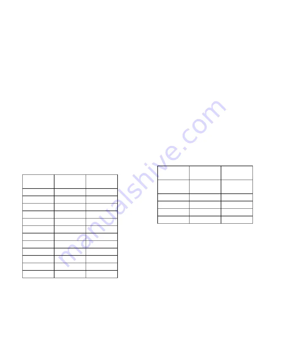
RECOMMENDED TURNING SPEEDS

WARNING. Turning too fast  for the  size of your work may result in injuring yourself or damaging the lathe!

Work piece 
Diameter

Max RPM 
Roughing

Max RPM 
Finishing

1”

3600

3600

2”

3000

4000

3”

2000

2600

4”

1500

2000

5”

1200

1600

6”

1000

1330

7”

850

1100

8”

750

1000

9”

660

900

10”

600

800

11”

540

725

12”

600

660

Maximum Speeds for Balanced Turnings

Multi Speed Chart for TCLC10

Max work 
piece dia.

Max Speed

Roughing
9”

Finishing
10” 

610

6”

8”

1000

4”

5.5”

1450

3”

4”

2000

2” or less

2.5”

3000

 Chart for TCLC10VS & TCLC12VS

Tool Rest (6)


- The tool rest is used to steady the cutting tool while the lathe is in operation. You can position the tool 

rest by releasing the lock handle(28) positioned on the side of the rest and sliding the rest into the desired position. 
Tighten the lock handle to secure the tool rest into position. The height of the tool rest can be adjusted releasing the 
lock handle(27) located on the front of the rest and adjusting the height to the desired position and then tightening the 
lock handle.
The position of the entire tool rest can be adjusted by reaching under the bed and loosening the clamp nut. Slide 
the rest into position. Tighten the clamp nut. The tool rest should be positioned just above the center line of the work 
piece. 

Note: The lock levers are spring loaded. To operate, pull out on the lever, rotate it on the pin, and then release.

Changing Belt Speeds

 -


Make sure the lathe is unplugged. Loosen the knob on the cover plate. Slide the cover up 

and off the lathe. Loosen the motor plate ratchet handle (10) to allow the motor plate to swivel upwards. To change the 
speed, move the belt drive from one pulley to another. (Note, Always go from the larger pulley to the smaller pulley) 
After moving the belt, tighten the motor pulley with the ratchet handle (10)- this also tightens the belt. Turn your latheês 
power on, and make sure that the belt is running consistently in its parallel groove (this should be done with the hand 
wheel(9). If all is smooth, turn the power off, reattach the cover.

Replacing the Belt

 - 

The Turncrafter Commanders are designed with a special feature that allows quick and easy belt changes.


Loosen belt, `Remove old belt


Slide the new belt over the headstock spindle pulley and onto the motor pulley.

Summary of Contents for TCLC10

Page 1: ...Turncrafter Commander Lathes User Manual Applies to models TCLC10 TCLC10VS TCLC12VS Read this manual completely before usage Model shown TCLC12VS www psiwoodworkingproducts com...

Page 2: ...tension cords that have 3 prong grounding type plugs and 3 hole receptacles that except the tool s plug 16 Check the speed BEFORE mounting any material onto the lathe ALWAYS start the lathe at its slo...

Page 3: ...eadstock Thread 1 x 8tpi 1 x 8tpi 1 x 8tpi Between Centers 18 18 18 Construction Cast Iron Cast Iron Cast Iron Swing over bed 10 10 12 Weight 83lbs 82lbs 106lbs Footprint 31 x 7 1 4 31 x 7 1 4 32 x 10...

Page 4: ...loose parts 2 Inspect the contents of the carton for shipping damage Compare the contents of the loose parts list provided Report any missing or damaged parts to your distributor 3 Keep the carton and...

Page 5: ...ver 10A 11 Speed Control VS Models 12 Power Switch 13 Spindle Lock Knob 14 Index Indicator 15 Cord Wrapping Supports 16 Tool Holder rack 17 Knockout Rod 18 Work Light BULB NOT INCLUDED 19 Mounting Hol...

Page 6: ...e Test work light switch 8 Dial speed to lowest speed Make sure spindle turns freely and free from loose parts or obstructions Turn on lathe Test speed knob 11 from slow to fast VS Models only GENERAL...

Page 7: ...ting to adjust the quill s extension The tailstock lock 28 locks the tailstock in its current position on the bed in relation to the headstock Release to move the tailstock assembly closer or further...

Page 8: ...indexing operation Next unscrew the index pin so that it frees the spindle and rotate the next spindle position Con tinue until all operations are completed Always back the index pin out completely be...

Page 9: ...The position of the entire tool rest can be adjusted by reaching under the bed and loosening the clamp nut Slide the rest into position Tighten the clamp nut The tool rest should be positioned just a...

Page 10: ...the chuck optional Pen Making Work mounts on pen mandrel secured between centers Requirements pen mandrel Drilling Work mounted on headstock 2MT drill chuck mounted in tailstock Requirements lathe chu...

Page 11: ...m rough round to a near finish A favor ite for pens Scrapers For smoothing and for interior clean up inside a bowl after gouge work is completed Bowl Gouges Used for hollowing out bowl centers Used on...

Page 12: ...12 10 12 Variable Speed Models TCLC10VS and TCLC12VS Part List...

Page 13: ...Lock bolt 1 46 2 Spring 1 46 3 Bolt 1 1 3 Washer 8 4 22 Drive pulley 1 22 1 Hex socket taper screw M6x12 1 23 Side protection guard 1 24 Hand wheel 1 24 1 Hex socket screw M6x12 2 25 Side plate 1 25...

Page 14: ...14 TCLC10 Part List...

Page 15: ...Connecting stand 1 29 1 Semi circle head screw M3x12 1 29 2 Washer 1 29 3 Hex nut 1 30 Rear plate 1 30 1 Moving knob 1 30 2 Stationary knob 1 30 3 Lock screw 1 30 4 Screw 1 31 Toolrest 1 32 Toolrest b...

Page 16: ...ug in cord from the headstock C 4 Plug MALE end of power cord into 110v power outlet Motor connection motor to control box pre attached Power connection Speed input motor to headstock pre attached TCL...

Page 17: ...tach the lead wire plug from the motor to the headstock socket over for motor connections Now you are ready to turn on your lathe Maximum Speed For Balanced Turnings Maximum RPM Roughing Maximum RPM F...

Page 18: ...Connecting the Motor to the Board Lead from Motor Connection in Headstck A A TCLC12VS Assembly 10 10 v2...

Page 19: ...2010 PSI Woodworking Products V 510...

Reviews: