


PS Engineering Inc. ®
PAR200A Audio Selector Panel, COM radio Controller and Intercom System
Installation and Operator’s Manual
200-228-0200
Page 2-11
Rev. 4, DEC. 2017
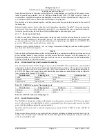
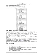
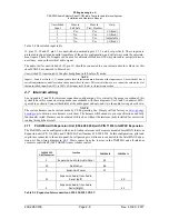
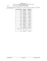
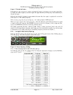
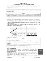
Pilot Microphone
J5
1
OFF
ON
2
ON
OFF
Copilot Microphone
3
OFF
ON
4
ON
OFF
J4
Passenger 1 Microphone
1
OFF
ON
2
ON
OFF
Passenger 2 Microphone
3
OFF
ON
4
ON
OFF
Table 2-6 Microphone gain settings
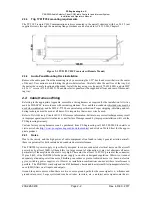
2.10 Communications Antenna Installation Notes
2.10.1 Antenna Location
For best results while in Split Mode, we recommend that the one VHF communications antenna is located
on top of the aircraft while the other communications antenna is installed on the bottom. Any antenna relo-
cation must be accomplished in accordance with AC 43.13-2B, aircraft manufacturers’ recommendations,
and other FAA-approved technical data.
WARNING
It is probable that radio interference will occur in the split mode when the frequencies of the two air-
craft radios are adjacent, and/or the antennas are physically close together.
PS Engineering makes no
expressed or implied warranties regarding the suitability of the PAR200A in Split Mode.
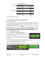
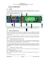
2.11 TY91/92(L) Adjustments
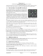
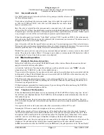
2.11.1 Radio Sidetone & Radio Squelch Adjustment
To change the automatic squelch threshold and sidetone level for the Trig
TY91/92 transceiver: Enter the Radio Volume mode by pressing the ICS but-
ton until the setup screen appears
Turn the outer knob to set the squelch threshold to low (weak signals open),
medium (normal operation) or high (blocks RF noise, requires stronger sig-
nals to open).
Turn the smaller inner knob to increase or decrease the radio sidetone. Typ-
ically, the radio sidetone is adjusted slightly lower volume than he received radio signals.
2.11.2 Radio Frequency spacing, 25 kHz or 8.33 kHz
Hold the “MUTE” button on the left side for 3 seconds, which will toggle between either 25 kHz spacing or
8.33 kHz spacing. This will be displayed on the LCD screen.