Building your MINI+
18
Original Prusa MINI+ semi-assembled
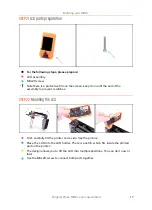
STEP 23
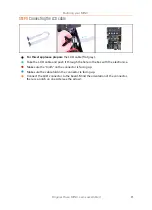
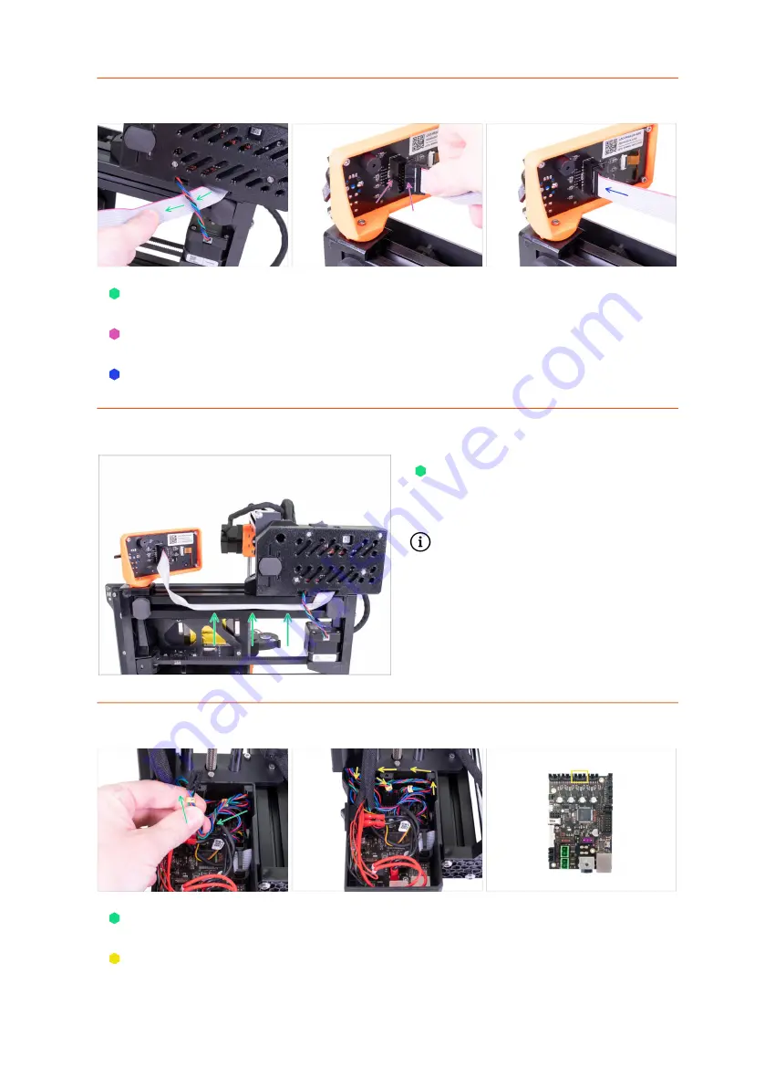
Connecting the LCD
Carefully remove the free end of the LCD cable from the box with the electronics
and guide the cable between the Y-axis motor cable and the extrusion.
Connect the cable to the board on the LCD. Mind the correct orientation of the
connector. Use the notch as a guide
Insert the connector in the socket on the board. Make sure it is all the way in.
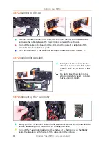
STEP 24
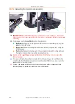
Guiding the LCD cable
Gently insert the cable inside the
extrusion. Leave some slack outside
near the LCD, so you can tilt it later
on.
Pro tip: to insert the cable in the
extrusion carefully bend it into two
halves along its length.
STEP 25
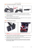
Connecting the Y-axis motor
Gently pull the Y-axis motor cable into the electronics. Do not stretch the cable. Do
not use excessive pulling force. You can damage the cable.
Connect the Y-axis motor cable into the empty slot in the top row on the Buddy
board. Create a loop with the rest of the cable like in the picture.
Summary of Contents for MINI+
Page 2: ...2 ...
Page 3: ...Original Prusa MINI semi assembled 3 Manual changelog MINI semi assembly ...
Page 5: ...Original Prusa MINI semi assembled 5 Building your MINI ...
Page 27: ...27 Notes ...
Page 28: ...28 ...
Page 29: ...29 Notes ...
Page 30: ...30 ...
Page 31: ...31 Notes ...
Page 32: ...32 ...

