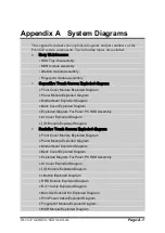
Appendix A System Diagrams
PA-5822 SERIES USER MANUAL
Page: A-15
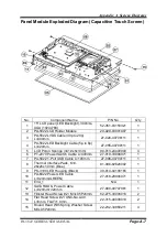
Motherboard Exploded Diagram (Resistive Touch Screen)
No.
Component Name
P/N No.
Q’ty
1
Front Cover Module
N/A
1
2
Panel Module
N/A
1
3
HSF, PA-6722 MB, for OBM, w/o reboot
MCU, with external RTC
PB-6722RB-A1N
1
4
PA-5822 LED LENS(Transparency)
90-021-02130407
1
5
Double Tape
N/A
1
6
Lens EVA
N/A
1
7
PT-1470 Speaker Cable L=350mm
27-021-28307071
1
8
PA-6225 2ND-DIS Power Cable (3p to
3p) L=115mm
27-012-31403072
1
9
PA-5822 MSR PS/2 (i-BUT) Cable (2p to
2p) L=440mm
27-022-40709071
1
10
Fillister Head Screw #1 / M3x0.5Px3L,
H=5mm
22-272-30008015
2
11
Round Head With Spring Washer Screw
M3x0.5Px6mm
22-232-30060211
7
12
Pan Head Screw T3.0x6mm
22-132-30060011
14
13
HEX CU Boss No.4-40,L=4.8,H=7mm
22-692-40048051
2
14
Flat Cable Clamp
30-042-04100258
2
Summary of Contents for PA-5822 M1
Page 10: ...vii Figure 3 26 Boot Menu Screen 3 52 Figure 3 27 Save Exit Menu Screen 3 54...
Page 32: ...Chapter 2 Hardware Configuration PA 5822 USER MANUAL Page 2 11 Jumper Diagrams Jumper Settings...
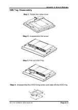
Page 119: ...Appendix A System Diagrams PA 5822 SERIES USER MANUAL Page A 2 HDD Tray Disassembly...
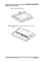
Page 120: ...Appendix A System Diagrams PA 5822 SERIES USER MANUAL Page A 3 MSR module Assembly...

