26
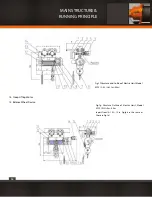
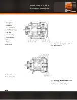
Fig.7b The Double-motor Group of Electric Hoist Model MDI 10t
2.2.3 Electric Devices
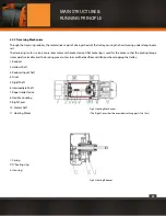
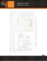
The electric devices of the electric hoist Model CDI, MDI consists of Control Cabinet, Push Button Station and Power-cut Space Limi-
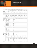
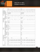
ter. The electrical principle scheme refers Fig. 9a~9b (Electricity Components in the Fig. please refer Table 2).
Control Cabinet is mounted to electric trolley with a connecting shelf. The stationary type of hoist will be fixed according to field
condition by users. The electric units should be fixed and fitted at the connecting board, while the cable is connecting with terminal
panel. The electricity control and operation is at safety voltages( normally is 36v).
The power-cut space limiter is used to prevent accident which may be caused by the loads exceeds the limited position when it goes
up or down. When the load reaches the limit position,the Rope Guide Device in Fig.1a(10) which moves axially impacts against the
Stop Block Fig.1a(11) on the space limiting lever, causing the space limit lever to push (or pull) the limiter so as cut off the circuit of
hoisting motor, then the load will stop moving. Push the button of the opposite direction, the load will disengage from the stabled
condition.
Be care the power-cut space limiter will not be used as path switch.
MAIN STRUCTURE &
RUNNING PRINCIPLE
Summary of Contents for PWMD Series
Page 1: ...1 PWMD and PWMDF SERIES User Manual and Security Warnings...
Page 17: ...17 MAIN STRUCTURE RUNNING PRINCIPLE...
Page 18: ...18 MAIN STRUCTURE RUNNING PRINCIPLE...
Page 19: ...19 MAIN STRUCTURE RUNNING PRINCIPLE...
Page 20: ...20 MAIN STRUCTURE RUNNING PRINCIPLE...
Page 21: ...21 MAIN STRUCTURE RUNNING PRINCIPLE...
Page 22: ...22 MAIN STRUCTURE RUNNING PRINCIPLE...
Page 28: ...28 MAIN STRUCTURE RUNNING PRINCIPLE...
Page 29: ...29 MAIN STRUCTURE RUNNING PRINCIPLE...
Page 33: ...33 PRECAUTION AND TROUBLE SHOOTING...
Page 66: ...66 b PWMD3T24M TECHNICAL SPECIFICATIONS...
Page 67: ...67 c PWMD5T24M TECHNICAL SPECIFICATIONS...
Page 68: ...68 d PWMD10T24M TECHNICAL SPECIFICATIONS...
Page 69: ...69 e PWMD16T24M TECHNICAL SPECIFICATIONS...
Page 70: ...70 f PWMD20T24M TECHNICAL SPECIFICATIONS...
Page 71: ...71 g PWMD25T18M TECHNICAL SPECIFICATIONS...
Page 72: ...72 h PWMD50T12M TECHNICAL SPECIFICATIONS...
Page 73: ...73 i PWMD50T20M TECHNICAL SPECIFICATIONS...
Page 74: ...74 j PWMDF3T24M TECHNICAL SPECIFICATIONS...
Page 75: ...75 k PWMDF5T24M TECHNICAL SPECIFICATIONS...
Page 76: ...76 l PWMDF10T24M TECHNICAL SPECIFICATIONS...
Page 77: ...77 m PWMDF16T24M TECHNICAL SPECIFICATIONS...
Page 78: ...78 n PWMDF20T24M TECHNICAL SPECIFICATIONS...
Page 79: ...79 o PWMDF25T18M TECHNICAL SPECIFICATIONS...
Page 80: ...80 p PWMDF32T18M TECHNICAL SPECIFICATIONS...
Page 81: ...81 q PWMDF50T12M TECHNICAL SPECIFICATIONS...
Page 82: ...82 r PWMDF50T20M TECHNICAL SPECIFICATIONS...
Page 84: ...84...


