15
2.2 Main structure and Running Principle of the Model CD1 & MD1 Electric Hoist
The hoist is formed of three parts. Hoisting Mechanism, Traversing Mechanism (stationary type has no trolley), Electric Control De-
vice.
MDI electric hoist is supplied with the base frame of CDI electric hoist. The hoisting motor is changed to double motor providing
normal and slow lifting speeds. The difference between MDI & CDI hoist are only hoisting motor and electric control parts.
2.2.1 Hoisting Mechanism
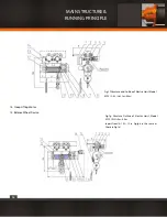
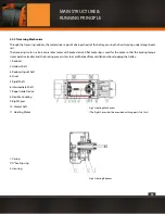
The hoisting mechanism of MDI & CDI hoist referring to fig.2.
The running principle is described as follows. The Hoisting Motor(11), through Flexible Coupling (8) , then the gears of the Reducer
(1), transmitted to the Hollow Shaft (2), then drives Drum (4) turning, cause the wire rope wound around the drum to draw the hook
device up and down.
The hoist with the lifting height H=6m,a Flexible Coupling (8) is adopted to connect the Motor Shaft (10) with the Input Shaft (3)
of the reducer. The flexible coupling, consisting of a rubber ring lined with fibre of high strength and two split half-couplings, can
absorb the impact load and make compensation for the installation errors. A Rope Guide Device (7) is provided to prevent the wire
rope from winding in disorder.
For the hoist with H≥9m, an Intermediate Shaft(6) and a Rigid Coupling(5) are provided.
For the hoist with H≥18m,a Support(9)(integral with the Right Cover) is used to prevent the long intermediate shaft from being
damaged and rotating roughly or bent caused by trembling as it is very long.
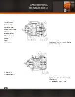
A transmitting mechanism of 3-stage outside meshed bevel gears is used for he reducer (See Fig.3). The gears and shafts are made
of alloy steel, quenched with carburization with the result of high strength and good wear-resistance. All the shafts are supported
by anti-friction bearings and well lubricated so that to have smooth transmission and ideal efficiency. “ O ” oil-proof rubber gasket is
used for the sealing between the housing and the case to ensure leak-proof.
The conic rotor motor of the electric hoist Model CDI has a built-in brake device (See Fig.4& 5). Switching on the power, the conic
rotor produces a magnetic pulling force along axial, which overcomes the pressure of the spring
to make the fan brake wheel disengage from Rear-cover and allow the motor running. When the power is cut off the magnetic
pulling force disappears, the cone braking lining, which stuck on the fan brake wheel and effected by the spring pressure, engages
tightly with the Rear-cover to make the brake. This brake is very reliable and the wear-resistance good, blades are designed on
the fan brake wheel, playing the role of heat dissipation and cooling.
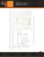
The hoisting motor of MDI electric hoist adopts a set of ZDSI double-motor group, the one consists of 3 parts (see Fig. 6 & 7a,( The
structure shown in the Fig.7b is used for the hoist of MDI 10t under some conditions.) those are Creep Hoisting Motor (1) (named
“small motor” in the following), Normal Hoisting Motor (2) (named “big motor” in the following), Creep Driving Mechanism (3). Their
running principle is introduced as follows.
MAIN STRUCTURE &
RUNNING PRINCIPLE
Summary of Contents for PWMD Series
Page 1: ...1 PWMD and PWMDF SERIES User Manual and Security Warnings...
Page 17: ...17 MAIN STRUCTURE RUNNING PRINCIPLE...
Page 18: ...18 MAIN STRUCTURE RUNNING PRINCIPLE...
Page 19: ...19 MAIN STRUCTURE RUNNING PRINCIPLE...
Page 20: ...20 MAIN STRUCTURE RUNNING PRINCIPLE...
Page 21: ...21 MAIN STRUCTURE RUNNING PRINCIPLE...
Page 22: ...22 MAIN STRUCTURE RUNNING PRINCIPLE...
Page 28: ...28 MAIN STRUCTURE RUNNING PRINCIPLE...
Page 29: ...29 MAIN STRUCTURE RUNNING PRINCIPLE...
Page 33: ...33 PRECAUTION AND TROUBLE SHOOTING...
Page 66: ...66 b PWMD3T24M TECHNICAL SPECIFICATIONS...
Page 67: ...67 c PWMD5T24M TECHNICAL SPECIFICATIONS...
Page 68: ...68 d PWMD10T24M TECHNICAL SPECIFICATIONS...
Page 69: ...69 e PWMD16T24M TECHNICAL SPECIFICATIONS...
Page 70: ...70 f PWMD20T24M TECHNICAL SPECIFICATIONS...
Page 71: ...71 g PWMD25T18M TECHNICAL SPECIFICATIONS...
Page 72: ...72 h PWMD50T12M TECHNICAL SPECIFICATIONS...
Page 73: ...73 i PWMD50T20M TECHNICAL SPECIFICATIONS...
Page 74: ...74 j PWMDF3T24M TECHNICAL SPECIFICATIONS...
Page 75: ...75 k PWMDF5T24M TECHNICAL SPECIFICATIONS...
Page 76: ...76 l PWMDF10T24M TECHNICAL SPECIFICATIONS...
Page 77: ...77 m PWMDF16T24M TECHNICAL SPECIFICATIONS...
Page 78: ...78 n PWMDF20T24M TECHNICAL SPECIFICATIONS...
Page 79: ...79 o PWMDF25T18M TECHNICAL SPECIFICATIONS...
Page 80: ...80 p PWMDF32T18M TECHNICAL SPECIFICATIONS...
Page 81: ...81 q PWMDF50T12M TECHNICAL SPECIFICATIONS...
Page 82: ...82 r PWMDF50T20M TECHNICAL SPECIFICATIONS...
Page 84: ...84...


