Provision CHALLENGER PRO Technical Manual Download Page 19

PRO  -  System  -  Technical Guide


13


Code  Number:[----]


1


2


3


4


5


6


7


8


9


0


PROGRAMMING 


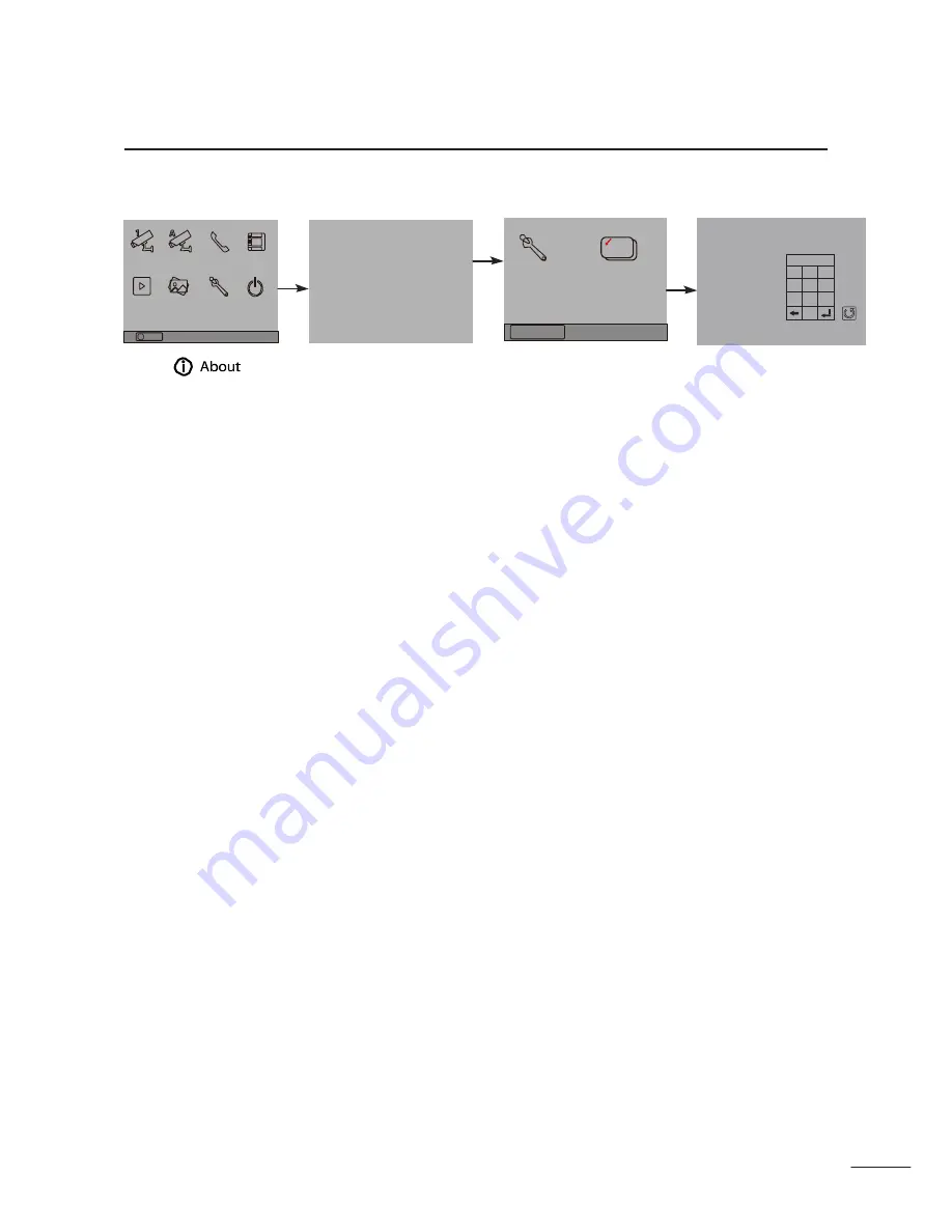
How to enter the installation setting page


Manual


Monitor


Monitor     Intercom    Multimedia


H/W :                            -- a1.3 
S/W:                             --- 
Local addr:                  --- 
Unlock timing:           --- 
Video standard:         - 


Installer 
setup


Caliber


TouchScreen


Installation settings: 

[0010]#:Remove all  remote control 
[0011]#:Add remote control


[8000]#:Set as  master unit  0 
[8001]#:Set as  slaver unit  1 
[8002]#:Set as  slaver unit  2 
[8003]#:Set as  slaver unit  3 
[8004]#:Set as  guard  unit 
[8005]#:Set as  not  guard   unit


[8006]#:Panel on  as  slaver unit  called 
[8007]#:Panel off  as  slaver unit  called 
[8008]#:Date format:MM/DD/YYYY 
[8009]#:Date format:DD/MM/YYYY 
[8010]#:Set lock  mode   to  0 [8011]#:Set 
lock  mode   to  1


Memory     Album       User Setup    Close


Playback


UI-CODE: 

--- 

MCM-VER.: 

--- 

Updated: 

--- 

Home


[8021]~[8029]


#Set  the  lock  time  of  1~9s


Multi  language settings:


---


Cancel


About


09/30/2010   Thu.16:41


1.Touch 

item 

on main menu page.


2.Touch the screen any - 
where and hold for 2s.


3.Touch  Installer  setup 
item


4.A digital keypad and in - 
structions will be showed.


Summary of Contents for CHALLENGER PRO

Page 1: ...CHALLENGER P R O 2 WIRE Video Intercom System Technical Guide...

Page 2: ...ntroduction 1 System Features 1 Home Applications 2 Apartment Applications 3 System Function 4 5 Section2 Units and Installations 6 Door Station 6 Parts and functions 6 Place Name Plate 7 Adjusting Ca...

Page 3: ...es and Distance 25 System Wirings and Connections 26 1 Basic one to one wiring and Cable Length 26 2 Multi monitors IN OUT wiring mode 27 3 Multi monitors Star wiring mode 28 4 Multi Door Stations sta...

Page 4: ...offers a variety of door stations to suit the fussiest of customers Choose from the super slim wall desktop mounted 3 5 PRO16 through to the 10 PRO21 all with colorful interface and touch screen opera...

Page 5: ...1 Home Applications Supports up to 16 monitors and 4 door stations 2 lock are also supported at each entrance...

Page 6: ...Apartment Applications Supports up to 32 monitors and 4 door stations 1 lock is also supported at each entrance...

Page 7: ...ng Touch screen operation with friendly interface Intercom by name list and selective intercom Selective monitoring each door stations or CCTV cameras Inner 128M flash picture memory and extended SD c...

Page 8: ...lay Camera adjustable Night view Additional features Calling from door station Dual communication with external unit Dual intercom communication between indoor units Unlock during calling conversation...

Page 9: ......

Page 10: ...ngle adjustable Night view LED Backlight name plate DIP switches for multi door station configuration Direct connect to electronic lock of 12Vdc Exit button Plug in connector to connect bus line PRO59...

Page 11: ...screwdriver to loosen the screw and then adjust the angle of the camera then fix the screw Electronic Specifications Power Supply DC 24V supplied by PROS4 24V or PROS5 24V Power Consumption Standby 5...

Page 12: ...6 Door Station Mounting Mounting Without Rainy Cover 1 160 165cm 2 3 1 2 4 Mounting With Rainy Cover 1 160 165cm 2 3 1 2 4...

Page 13: ...k power input connect to the power positive power S1 S2 Lock power output to connect 2 locks S Lock power output connect to the power input of locks only when using the camera to power the locks if us...

Page 14: ...set to 0 by default Connect one lock Connect two locks Connect one lock Connect two locks Jumper position in 1 2 Jumper position in 1 2 BUS PL S1 S2 S BUS PL S1 S2 S EB LOCK EB EB 2nd 1ST LOCK 2nd 1S...

Page 15: ...ngs 0010 Remove all remote control 0011 Add remote control 8000 Set as master unit 0 8001 Set as slaver unit 1 8002 Set as slaver unit 2 8003 Set as slaver unit 3 8004 Set as guard unit 8005 Set as no...

Page 16: ...ation Picture memory optional Using DIP for Monitor ID setting Using plug in connector On screen name list for intercom No additional power supply needed supplied by system Additional door bell call b...

Page 17: ...nit Monitor when the guard unit Monitor answers the call conversation with the guard person is started Please refer to section 4 system setup installation setup how to set the monitor as a guard unit...

Page 18: ...Ctrl A to select all click the right key of the mouse choose transfer selected to JPG item save the pic tures on computer When the built in memory is full the oldest picture will be deleted to make r...

Page 19: ...s slaver unit 2 8003 Set as slaver unit 3 8004 Set as guard unit 8005 Set as not guard unit 8006 Panel on as slaver unit called 8007 Panel off as slaver unit called 8008 Date format MM DD YYYY 8009 Da...

Page 20: ...rs two methods of date and time 8009 is used to set the date format as date month year 8008 is used to set the date format as month date year 8012 is used to set the time format as 12 hour system 8013...

Page 21: ...IVATION The unlock time can be set from 1 to 9 seconds The code number from 8021 to 8029 are used to set the unlock time to 1 9 seconds as indicated above How to set the menu language for SD model onl...

Page 22: ...OK 1 2 3 4 In standby mode touch the unlock button and hold for 2s icon will be shown on screen then touch icon until the icon move to next location The same as last operation The same as last operati...

Page 23: ...Code setting The value is from 0 to 31 which have 32 different codes Bit state User Code Bit state User Code Bit state User Code ON ON ON Code 0 Code 11 1 2 3 4 5 6 1 2 3 4 5 6 1 2 3 4 5 6 ON 1 2 3 4...

Page 24: ...Door Station Monitor Extending Connection Manual Monitor Monitor Intercom Multimedia Memory Playback Album User Setup Close About 09 30 2010 Thu 16 41 L1 ON DIPS L2 1 2 3 4 5 6 L 1 ON D IP S L 2 1 2...

Page 25: ...ing when the Monitor rejected or answered the call 12Vdc 300mA SW SW EXT RING GND VIDEO 3 TV out function Connect television to the Monitor when the Door Station calls the user switch the channel to t...

Page 26: ...to 32 Monitors Support up to 4 Door Stations Dimension and Terminal 152 5 L AC N AC V V V V VADJ LED L AC AC input N AC AC input Earth Ground V DC power output 21 5 26 5 adjustable V DC power output 2...

Page 27: ...the suitable power for the non polarity bus Note that the PRODPS must work together with the PROS5 or PROS4 power supply Connect to PRODPS Power Supply PROS5 24V Connect to Door Station Connect to Mo...

Page 28: ...st one at the end of the line needs one DBC to connect to the Non polarity Bus Line No extra power supply needed and one LED indicator to show the working state PRODBC Bus In Out Bus Out to Monitor Te...

Page 29: ...s a 2 wire branch controller with 4 outputs distributor for the Challenger Pro system to approach the star topology connection in the apartment system See Section 3 Cables and Connection for detail co...

Page 30: ...24 Technical Specifications PRODBC4S Power Supply DC24V Temperature 100 C 400 C Wiring 2 wires non polarity Dimension 88 H 140 W 32 D mm PRODBC4S Dimensions...

Page 31: ...tem Technical Guide 25 88mm 13mm 36mm 62mm 140mm 70mm upward 32mm 84mm Trunk Bus D C B A HI A B C D port Connect to Monitors Door Station Trunk Bus Bus input output 120 Direct Wall Mounting DIN Rail M...

Page 32: ...Height The recommended installation height of both Door Sta tion and Monitor is from 160 165 cm 1 2 3 4 160 165 cm Door Station Install Condition The Door Station cannot be installed in a place that h...

Page 33: ...different cables may also effect the maxi mum distance the system can reach The farest monitor 1 2 3 4 DBC 1 1 2 2 3 3 4 4 C When Monitor quantity 20 DPS PS5 A When Monitor quantity 20 Cable Usage A...

Page 34: ...wisted Cable 2X0 75 mm2 60 100 40 Twisted Cable 2X1 0 mm2 80 120 60 Here is a table for description of the two power supplies Item Input Output Application PROPS4 24V AC 100 240V DC 24V 1A Just can po...

Page 35: ...em Technical Guide 29 2 2 2 Multi monitors IN OUT wiring mode ON 1 2 3 4 5 6 1 3 4 Code 15 DIP 6 on ON 1 2 3 4 5 6 1 2 3 Code 14 DIP 6 off 4 ON 1 2 3 4 5 6 1 3 4 Code 0 DIP 6 off DPS PS5 85 260AC ID 0...

Page 36: ...2 3 HI 1 2 3 4 5 6 2 3 4 Code 15 DIP 6 on Code 14 DIP 6 on 4 ON ON 1 2 3 4 5 6 1 1 2 3 4 5 6 2 3 4 Code 13 DIP 6 on 3 Code 12 DIP 6 on 4 ON ON 1 2 3 4 5 6 1 3 4 Code 3 DIP 6 on 1 2 3 4 5 6 2 3 4 Code...

Page 37: ...stem must be programmed with a calling address or calling number which is User Code For Monitor User Code is defined by 1 5 bits DIP switches on the connection board according the User Code rules For...

Page 38: ...he screen by default Programming Slave User Code is by means of Monitor Menu for more detailed operation please refer to the followings as below Installation setup on monitor How to set the monitor as...

Page 39: ...Name Label Remark ON 00 1 2 3 4 5 6 ON 01 1 2 3 4 5 6 ON 02 1 2 3 4 5 6 ON 03 1 2 3 4 5 6 ON 04 1 2 3 4 5 6 ON 05 1 2 3 4 5 6 ON 06 1 2 3 4 5 6 ON 07 1 2 3 4 5 6 ON 08 1 2 3 4 5 6 ON 09 1 2 3 4 5 6 ON...

Page 40: ...mark ON 16 1 2 3 4 5 6 ON 17 1 2 3 4 5 6 ON 18 1 2 3 4 5 6 ON 19 1 2 3 4 5 6 ON 20 1 2 3 4 5 6 ON 21 1 2 3 4 5 6 ON 22 1 2 3 4 5 6 ON 23 1 2 3 4 5 6 ON 24 1 2 3 4 5 6 ON 25 1 2 3 4 5 6 ON 26 1 2 3 4 5...

Page 41: ...PRO System Technical Guide 35 Provision Security Products Pty Ltd www provisioncctv com au PRO System Technical Guide_V1 0...

Page 42: ...s After finishing communication press TALK MON button again or touch icon to end the communication If nobody answers the phone the screen will be turned off automatically after 30 seconds 3 During tal...

Page 43: ...ling Next Page Intercom Call 00 Jim Zhang 01 Calo Liu 02 Jacko Zhang 03 Philips Chen 04 Hebe Zhang 05 Tony Li 6 Basic Setup Instructions Ring Tone Settings Touch User Setup item on main menu page to e...

Page 44: ...ch icon to get into main menu page Cancel Home Save Exit Monitor Time Select Current 01min Ring Volume and Night Ring Volume Setting You can set a ring volume for day time and night time individually...

Page 45: ...uard person is started The code number of 8004 is used to set the monitor as a guard unit monitor and 8005 is used to cancel this function Exit Home User Setup 2 Ring Volume Night Ring Volume TPC Conf...

Page 46: ...ave monitors so you should set the address correctly note must have one monitor to be set as master monitor The code of 8000 is used to set the master monitor The code of 8001 is used to set the first...

Page 47: ...6 Dutch 8107 Portuguese 8108 S Chinese 8109 T Chinese 8110 Greek 8111 Turkish 8112 Polish 8113 Russian 8114 Slovakia 8115 Hungray 8116 Czech Note the monitor can only support 4 types of languages Engl...

Page 48: ...y setting adjust the value to get the best image you like 3 The Ratio item is for screen display adjustment you can set to 16 9 or 4 3 4 The Talk Volume item is for talking volume adjustment 5 Note th...

Reviews: