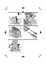
(Fig. 1 and 2)
12
Further adjustment is provided by the parallel fence (13)
and the adjustable pointer (14).
For 230 V:
The incorporated soft-start
/
brake electronic circuit
„SSB electronic“ provides for soft starting when the electric
tool is switched on, as well as short rundown time
of approx. 7 s when the electric tool is switched off.
Adjustment of the notcher
For transport, for most adjustment works and tool
replacement, it is recommended to use a transport cart
and support the electric tool with suitable wooden baulks
in fixed positions.
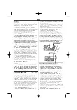
Even before the notcher can be adjusted, the notch, flat
joint or groove to be cut must be allocated and marked
on the workpiece.
To check correct positioning of the scales preset in the
factory, perform the following:
– Place the notcher on the workpiece
– Release the locking lever (15)
– Set the cutting depth to „0“ by means of the hand
wheel (12)
– Set the slide ruler (11) to 30° bevel angle
– Tilt the milling unit to 30° - see the description in
the section „Adjustment for cutting rafter seats“
– Turn the cutting head in the working direction, using
the hexagon key (16); cutting edges of the blades must
be flush with the surface of the workpiece.
If readjustment is necessary, determine the „0“ position
by turning the cutting head and adjusting the cutting
depth simultaneously. Loosen both the screws (17) of the
scale (18), set the „0“ mark towards the slide ruler and
retighten the screws.
The bevel angle and cutting depth (measured in the
direction of plunging movement) are to be determined
from the outline of rafter seat or notch marked on the
workpiece.
Adjustment for cutting rafter seats
– Install the rafter-seat cutting head (see Figure 3)
– Insert the parallel fence (13) adjacent to the cutting
head and push so far that it may be fixed with all
the four wing screws (19)
– Adjust the sliding ruler (11) to the required angle
of rafter seat (e.g. 30°)
– Loosen both the locking levers (20
/
21) on the hinge
fixtures, tilt the milling unit (e.g. to 30° bevel angle)
and retighten both the locking levers
– Adjust the required cutting depth (measured in the
direction of plunging movement) according to the scale
(e.g. 50 mm) by means of the hand wheel (12) after
loosening of the locking lever (15) and retighten
the lever after adjustment is completed
– Slide the adjustable pointer (14) according to its scale,
depending on the adjusted bevel angle (e.g. 30°)
– Check adjustment of the notcher and tightening of
all the fixing elements
– Align the guide rail (accessory) or a straight lath parallel
to the marked line and fix it to the workpiece.
Adjustment for cutting flat
joints or grooves
– Set the milling unit to its basic position with 0° bevel angle;
– Install the flat cutting head (see Figure 3)
– Insert the parallel fence (13) adjacent to the cutting head
and firmly fix with the four hand screws (19)
– Adjust the sliding ruler (11) to the position „Abplatten“
– Adjust the required cutting depth by means of the hand
wheel (12) after loosening the locking lever (15) and
retighten the lever after adjustment is completed
– Align the adjustable pointer (14) with the appropriate
side of the cutting head
– Check adjustment of the notcher and tightening of all
the fixing elements
– Align the guide rail (accessory) or a straight lath parallel
to the marked line and fix it to the workpiece.
Adjustment for working
with the guide rail (accessories)
– Align the guide rail (22) parallel to the marked line
and fix it to the workpiece
– Place the notcher with the parallel fence (13) on the
guide rail
– Loosen all the four hand screws (19)
– Slide the notcher in such position that the pointer
GB
(Fig. 1 and 2)
(Fig. 1 and 2)
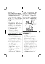
(Figure 4)
marked edge of the notch
width of cutting head
cutting depth
bevel angle
cutting depth
(plunge measurement)
Summary of Contents for NRP 90
Page 1: ...NRP 90 230 V NRP 90 400 V...
Page 3: ...1 2 5 3 3 4...
Page 73: ...12 15 14 22 13 19 8 400 V 1 3 16 23 24 25 73 GR 1 3 4...
Page 76: ...1 2 3 4 5 6 7 8 9 10 11 12 13 Fl PRCD 14 15 16 17 18 19 230 230 16 76 RUS...
Page 79: ...79 8 400 1 3 16 23 24 25 0 Silbergleit RUS 1 3...
Page 80: ...80 230 26 27 400 5 C 5 C N 50144 230 96 A 109 A 2 7 2 400 86 A 99 A 2 5 2 RUS...
Page 81: ...81 N 50144 1 N 55014 1 N 55014 2 N 61000 3 2 N 61000 3 3 89 336 C 98 37 C Manfred Kirchner RUS...
Page 99: ......
Page 100: ......

