Chapter 2 System Configuration
POS-3520 USER
’
S MANUAL
Page: 2-3
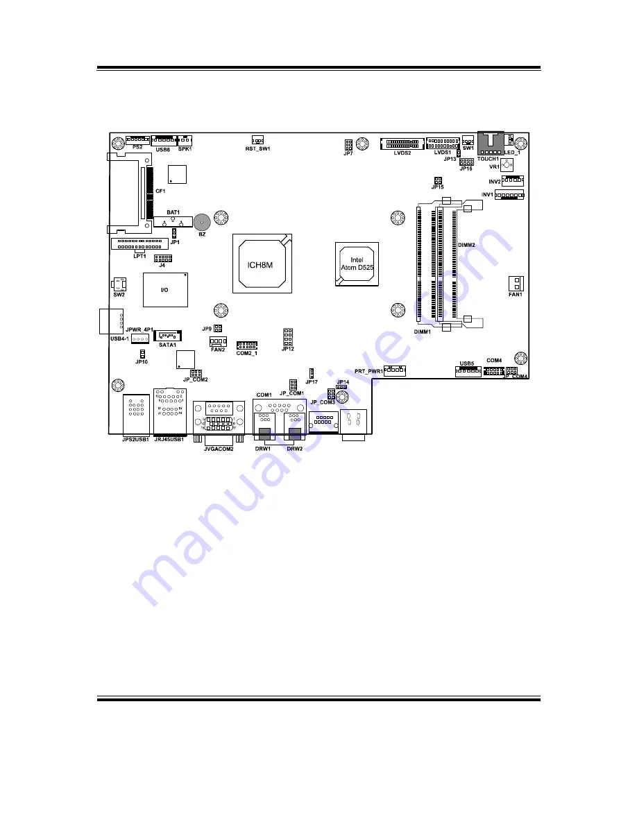
2-2. COMPONENT LOCATIONS
2
4
1
3
1
2
3
4
5
6
1
2
5
6
1
2
2
1
6
5
5
6
1
2
5
6
1
2
1
4
9
13
14
12
8
5
21
24
20
16
1
2
5
6
1
6
9
5
1
2
5
6
COM3
9
1
10
2
1
2
3
4
PWR_IN1
1
3
1
3
1
2
1
2
2
1
7
8
2
1
7
8
1
1
1
1
1
1
4
1
2
3
4
1
7
1
4
1
4
1
5
9
1
10
2
203
73
2
72
71
74
1
204
203
73
2
72 71
74
1
204
1
19
20
2
1
29
30
2
1
7
1
4
1
2
3
1
5
1
6
5
1
10
6
1
2
1
4
2
1
9
10
1
14
13
26
1
3
POS-3520 Connector, Jumper and Component locations
Summary of Contents for POS-3520
Page 1: ...USER S MANUAL POS 3520 15 POS System Powered by Intel Atom D525 Platform POS 3520 M6...
Page 18: ...Chapter 2 System Configuration POS 3520 USER S MANUAL Page 2 5 JUMPER DIAGRAMS JUMPER SETTINGS...
Page 76: ...Appendix A System Assembly POS 3520 USER S MANUAL Page A 3...
Page 77: ...Appendix A System Assembly Page A 4 POS 3520 USER S MANUAL...
Page 79: ...Appendix A System Assembly Page A 6 POS 3520 USER S MANUAL...
Page 80: ...Appendix A System Assembly POS 3520 USER S MANUAL Page A 7...
Page 84: ...Appendix A System Assembly POS 3520 USER S MANUAL Page A 11...
Page 85: ...Appendix A System Assembly Page A 12 POS 3520 USER S MANUAL...
Page 87: ...Appendix A System Assembly Page A 14 POS 3520 USER S MANUAL...
Page 90: ...Appendix A System Assembly POS 3520 USER S MANUAL Page A 17...
Page 92: ...Appendix A System Assembly POS 3520 USER S MANUAL Page A 19...
Page 95: ...Appendix A System Assembly Page A 22 POS 3520 USER S MANUAL...
Page 99: ...Appendix B Technical Summary Page B 2 POS 3520 USER S MANUAL BLOCK DIAGRAM...


