15
PRS-UM-BTN-EN-Rev02-02.2019
to Span button till the level reaches the necessarly value. Once the span calibration
completed remove the jumper and put as a spare on to detector board.
Important: Never put jumper on both S+ and S- pins and press any button.
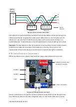
Diagram 11: Calibration buttons and pins
General Specification
BTN Series Detector Electrical Specifications:
Input Voltage Range
12 to 20VDC (16VDC nominal)
Max Power Consumption 0.96 Watts at 16VDC - normal condition
1.60 Watts at 16VDC - alarm and fault condition
Terminals
4 x 2 x screw terminals suitable for wire diameter 1.5mm2 to 2.5mm2
Relays
3 x (1A 30VDC, 0.5A 125VAC, 0.3A 80VDC).
Non-selectable: normally open and de-energized
Communication
RS485, Modbus RTU
Sensor
Catalytic
Table 2: BTN Series detectors electrical specifications
Detector Body Specifications:
Material
Plastic (black)
Weight
Plastic buat: 230g (with Sensor Header)
Mounting
Wall mounting
Entries
PG11
Table 3: Detector body specifications
Environmental:
IP Rating
IP54 (plastic buat)
Operating Temperature
-10ºC to +50ºC / 14ºF to +120ºF
Operating Humidity
Continuous 20-90%RH (non condensing)
Operating Pressure
90-110kPa
Storage Conditions
-10°C to +50°C (14°F to +120°F)
Table 4: Environmental specifications
Span (S) and Zero (Z) buttons
Span (S+ , S-) and Zero (Z) pins


