background image


19


PBD‐2555V   


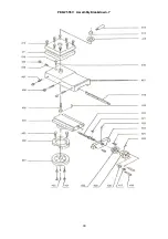
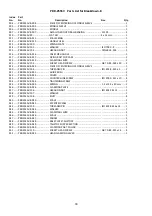
Parts List for  Breakdown ‐1


Index 

Part 


No. 

No. 

Description 

Size 

Qty. 

 
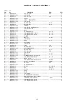
102 ....... PBD2555V‐1 ........................... FLAT KEY .................................................................. 4 x 12 mm ..................... 1 
107 ....... PBD2555V‐1‐107.................... LATHE BED ...............................................................  ..................................... 1 
108 ....... PBD2555V‐2 ........................... HEXAGON SOCKET SCREW M8

×

12 .........................  M8

×

12 ........................ 1 

109 ....... PBD2555V‐3 ........................... HEXAGON SOCKET SCREW M5

×

12 ......................... M5

×

12 ......................... 5 

110 ....... PBD2555V‐4 ........................... BALL OILER .............................................................. 6 ................................... 1 
111 ....... PBD2555V‐1‐111.................... RIGHT BEARING PEDESTAL  .....................................  ..................................... 1 
112 ....... PBD2555V‐5 ...........................  HEXAGON SOCKET SCREW M6

×

16 ........................   M6

×

16 ....................... 4 

113 ....... PBD2555V‐6 ........................... FLAT KEYTAPER PIN 6

×

22 ....................................... DIN6885 ....................... 2 

114 ....... PBD2555V‐1‐114.................... LEADSCREW ............................................................  ..................................... 1 
115 ....... PBD2555V‐1‐115.................... RACK ........................................................................  ..................................... 1 
116 ....... PBD2555V‐7 ........................... HEXAGON SOCKET SCREW M4

×

16 ......................... M4

×

16 ......................... 3 

117 ....... PBD2555V‐1‐117.................... ADJUSTING FLANGE ................................................  ..................................... 1 


Summary of Contents for PBD-2555V

Page 1: ...taux 06 2017 PBD 2555V Schweiz Suisse JPW TOOL AG T mperlistrasse 5 CH 8117 F llanden Switzerland www promac ch France TOOL France PROMAC 57 rue du Bois Chaland Z I du Bois Chaland case postale 2935...

Page 2: ...Directive Maschinenrichtlinie Directive Machines 2014 30 EU electromagnetic compatibility elektromagnetische Vertr glichkeit compatibilit lectromagn tique designed in consideration of the standards u...

Page 3: ...fications 7 8 5 0 Machine description 9 6 0 Setup and assembly 10 6 1 Unpacking and clean up 10 6 2 Shipping contents 10 6 3 Assembly 10 6 4 Initial lubrication 10 6 5 Installation 10 7 0 Electrical c...

Page 4: ...orm a habit of checking to see that keys and adjusting wrenches are removed from the machine before turning it on 15 Keep safety guards in place at all times when the machine is in use If removed for...

Page 5: ...working outfit Wear safety goggles Wear ear protection Always wear the approved working outfit Wear safety shoes Remove tie rings watches jewellery Roll up sleeves above elbows Remove all loose clothi...

Page 6: ...ting and changing accessories Do not attempt to adjust or remove tools during operation Never stop a rotating chuck or workpiece with your hands Choose a small spindle speed when working unbalanced wo...

Page 7: ...TPI Materials Machine Bed Cast iron induction hardened and precision ground Headstock tailstock slides Cast iron Spindle bearings Taper roller bearings quality level P5 Sound emission in idle 1 73 4...

Page 8: ...g Figure 4 1 Spindle nose mounting 4 2 Anchor bolt hole pattern Figure 4 2 Anchor bolt pattern for lathe bed left machine stand right WARNING To avoid tipping the machine must be bolted down with four...

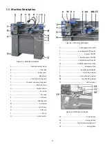
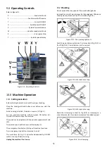
Page 9: ...Lead screw O Chip tray P Apron Q Anchor points Figure 5 2 Machine description R Feed speed select knob S Feed forward off reverse T Coolant ON OFF U Spindle power ON OFF V Spindle forward reverse W V...

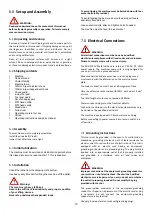
Page 10: ...and tighten bolts if needed The machine must be level to be accurate 7 0 Electrical Connections WARNING All electrical connections must be done by a qualified electrician in compliance with all local...

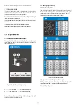
Page 11: ...olled by the variable speed select knob W Fig 5 2 as well as the position of the belt on the pulleys Fig 8 1 Figure 8 1 Spindle speed range setup A 50 1250 RPM for maximum torque B 100 2500 RPM for ma...

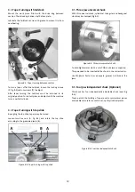
Page 12: ...e tapers may be turned Loosen two hex nuts A Fig 8 4 and rotate the top slide according to the graduated scale B Figure 8 4 Taper turning with top slide 8 5 Three jaw universal chuck With this univers...

Page 13: ...and follow rest The rests prevent flexing of long and thin work pieces under pressure from the tool The steady rest Fig 8 8 serves as a support for longer shafts and ensures a safe and chatter free op...

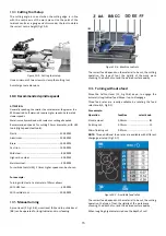
Page 14: ...eed select knob W The spindle speed will be shown on the display Y The emergency stop button X stops all machine functions Turn emergency stop button clockwise to reset The work lamp G Fig 5 1 operate...

Page 15: ...at a diameter of 20mm allows With HSS tool 400 RPM With carbide tool 2000 RPM 10 5 Manual turning Apron travel Z Fig 10 6 cross travel AA and top slide travel BB can be operated for longitudinal and...

Page 16: ...fore any intervention on the machine disconnect it from electrical supply pull the mains plug Failure to comply may cause serious injury An important security factor is the cleaning of the machine of...

Page 17: ...load too high Reduce depth of cut or feed Noisy operation Dry change gear hubs Lubricate with oil Dry change gears Lubricate with grease Tool tip burns Cutting speed too high Reduce spindle speed Dull...

Page 18: ...18 15 0 Replacement Parts PBD 2555V Assembly Breakdown 1...

Page 19: ...M8 12 M8 12 1 109 PBD2555V 3 HEXAGON SOCKET SCREW M5 12 M5 12 5 110 PBD2555V 4 BALL OILER 6 1 111 PBD2555V 1 111 RIGHT BEARING PEDESTAL 1 112 PBD2555V 5 HEXAGON SOCKET SCREW M6 16 M6 16 4 113 PBD2555V...

Page 20: ...20 PBD 2555V Assembly Breakdown 2...

Page 21: ...PBD2555V 18 THREADED PIN ISO 4028 M6X10 1 431 PBD2555V 2 431 MOTOR 110ZYT59T1 1 432 PBD2555V 19 FLAT KEY 4 x 30 mm 1 433 PBD2555V 20 WASHER 1 434 PBD2555V 21 HEXAGONAL NUT M8 DIN439 1 435 PBD2555V 2...

Page 22: ...22 PBD 2555V Assembly Breakdown 3...

Page 23: ...ING 1 321 PBD2555V 3 321 GEARWHEEL 1 322 PBD2555V 36 CIRCLIP 15 1 323 PBD2555V 37 FEATHER KEY 4 14 1 324 PBD2555V 3 324 LONG FACE PINION 1 325 PBD2555V 38 FEATHER KEY 4 10 1 326 PBD2555V 39 LOCK WASHE...

Page 24: ...24 PBD 2555V Assembly Breakdown 4...

Page 25: ...2555V 4 509 GEAR Z70 Module 1 5 1 510 PBD2555V 4 510 GEAR Z65 Module 1 5 1 511 PBD2555V 4 511 GEAR Z60 Module 1 5 2 512 PBD2555V 4 512 GEAR Z50 Module 1 5 1 513 PBD2555V 4 513 GEAR Z45 Module 1 5 1 51...

Page 26: ...26 PBD 2555V Assembly Breakdown 5...

Page 27: ...4 8 3 614 PBD2555V 58 HEXAGON SOCKET SCREW M4 8 3 615 PBD2555V 5 615 FLANGE PEDESTAL 1 616 PBD2555V 59 TAPER PIN 3 30 1 617 PBD2555V 5 617 HANDLE BAR 1 618 PBD2555V 5 618 HANDLE 1 619 PBD2555V 5 619 H...

Page 28: ...28 PBD 2555V Assembly Breakdown 6...

Page 29: ...6 CROSS SLIDE 1 517 PBD2555V 74 HEXAGON SOCKET SCREW M5 10 1 518 PBD2555V 6 518 WASHER 1 519 PBD2555V 75 HEXAGON SOCKET SCREW M8 10 2 520 PBD2555V 6 520 GUIDE BEAD 1 521 PBD2555V 6 521 GUIDE RAIL 1 52...

Page 30: ...30 PBD 2555V Assembly Breakdown 7...

Page 31: ...E HEAD BOLT M8 25 8 413 PBD2555V 7 413 HANDLE 1 414 PBD2555V 7 414 CLAMPING PIECE 1 415 PBD2555V 7 415 WASHER 1 416 PBD2555V 7 416 COMPRESSION SPRING 0 8X4X15 1 417 PBD2555V 7 417 TOP SLIDE 1 418 PBD2...

Page 32: ...32 PBD 2555V Assembly Breakdown 8...

Page 33: ...OF CENTERING OF SPINDLE SLEEVE 1 930 PBD2555V 104 THREADED PIN ISO 4028 M4 x 5 1 931 PBD2555V 8 931 GUIDE BUSH 1 932 PBD2555V 8 932 COVER 1 933 PBD2555V 105 COUNTERSUNK SCREW ISO 2009 M5 x 10 4 934 P...

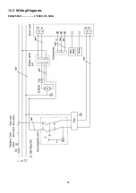
Page 34: ...34 16 0 Wiring Diagrams PBD 2555V 1 230V PE 50Hz...

Page 35: ...Note Electromagnetic switch KJD17GF 1 Reverse Switch F R ZH A 1 EMC Filter 1 Emergency stop ZB2 BE102C 1 Circuit board 1 Potentiometer WX14 12 4K7 1 Speed display and sensor JD011 5V 1 DC Motor 1 FU1...

Reviews: