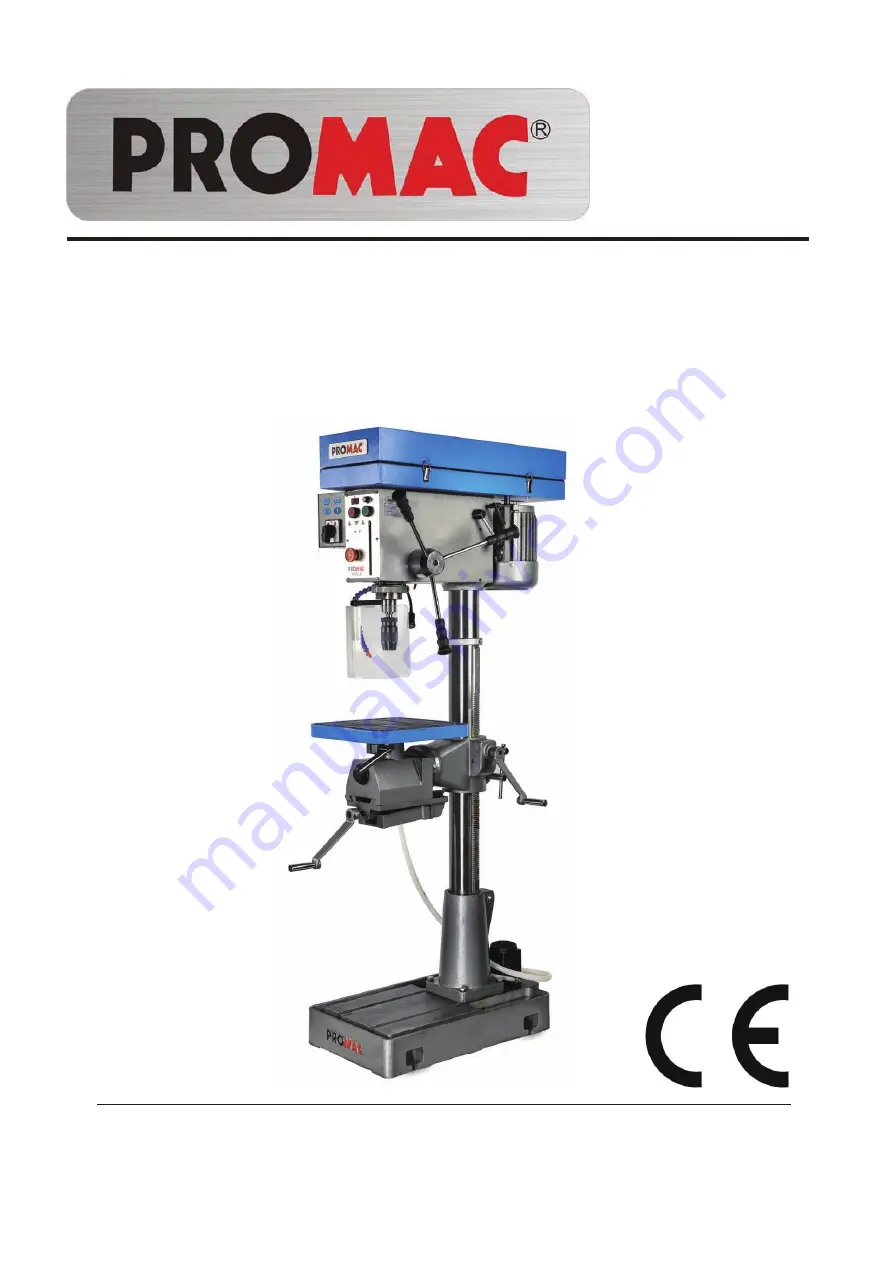
Promac 930ELB Operating Instructions Manual Download Page 1

930ELB

Drill press

Bohrmaschinen
Perceuses 

07-2016

Schweiz / Suisse

JPW (TOOL) AG

Tämperlistrasse 5

CH-8117 Fällanden Switzerland

www.promac.ch

France

TOOL France / PROMAC

57, rue du Bois Chaland, Z.I. du Bois Chaland

case postale 2935 FR-91029 Evry Cedex

www.promac.fr

Summary of Contents for 930ELB

Page 1: ...en Perceuses 07 2016 Schweiz Suisse JPW TOOL AG T mperlistrasse 5 CH 8117 F llanden Switzerland www promac ch France TOOL France PROMAC 57 rue du Bois Chaland Z I du Bois Chaland case postale 2935 FR...

Page 2: ...y Directive Maschinenrichtlinie Directive Machines 2014 30 EU electromagnetic compatibility elektromagnetische Vertr glichkeit compatibilit lectromagn tique designed in consideration of the standards...

Page 3: ...ease refer to instruction manual in specification and machine weight to arrange handling manner Be sure to use capable fork lifter or hoist to lift of machine 2 The handling and transportation shall b...

Page 4: ...the machine MODEL AREA SETTED SCREW 930ELB X 900 700 M12 2 The dimension of setting hole and Working Clearances Consider existing and anticipated needs size of material to be processed through each m...

Page 5: ...Motor Handle J Vice 3 C Motor K1 Table Lock K2 Table D Feed Handle L Chuck Guard E Depth Stop E1 Pump Valve Lock M Spindle F Locks table height N Control panel G Raises lowers table O High Low Switch...

Page 6: ...ten 2 Install the crank lever over the pinion shaft and tighten the setscrew in the crank handle against the flat part of the pinion shaft Figure 03 3 The drill chuck attaches to the spindle by means...

Page 7: ...separation and an unsafe condition Figure 05 06 07 2 Use the chuck key to adjust the jaws of the drill chuck until they are inside the drill chuck body Figure 08 09 3 Place the drill chuck face down o...

Page 8: ...lugs to avoid any noise from hurting the listening whilst operation Please do wear proper work clothing whilst operation Loose clothing or tie are prohibited to avoid any unnecessary incident If a ope...

Page 9: ...clothing gloves neckties ring and bracelet during operation Always wear safety glasses cap and specific clothes 9 Check all parts are in place and securely locked before transportation Bump and crash...

Page 10: ...voltage is for the machine B Make sure the machine is completely assembled and installed C Make sure chuck working table working piece are completely secured or tightly fixed D Make sure the chuck ke...

Page 11: ...dle shaft is in normal condition or not 2 The speed control switch controls spindle speed adjustment 3 If it needs to stop urgently just push the emergency stop switch 3 2 Operation illustration and p...

Page 12: ...Adjustment of feeding limit To prevent unwanted penetration to work piece the feeding limit shall be set by adjusting the appropriate position of feeding depth fixing button as long as the distance be...

Page 13: ...w then turn the work table 180 degree let the vise be upside Then completely tight the set bolt Figure 13 14 15 16 6 Please open water outlet valve and adjust a proper water outlet volume after power...

Page 14: ...725 350 1450 725 910 405 12 795 400 210 105 665 320 1330 665 745 370 13 735 365 195 100 610 295 1225 610 685 340 14 680 340 180 90 570 270 1135 570 635 320 15 640 320 170 85 530 255 1060 530 600 300...

Page 15: ...t belt tension 3 Lock knob B firmly to fix belt tension When speed change is required Loosen lead bolt on both side of headstock Pull belt handle to allow belts repositioning and then move belts to co...

Page 16: ...b and rotate the hub Figure 18 clockwise until it stops 4 Tighten the lock knob The quill should not return up into the head casting 5 Rotate the spindle until the inner drift key slot is aligned with...

Page 17: ...2 Cutting liquid in abnormal condition and cannot supply the adequate quantity 1 Check the pump is running or not 2 Check if the hose is leaking or not 3 Spindle shaft cannot running completely 1 Che...

Page 18: ...ch off power and remove plug from power source outlet before maintenance Everyday 1 week 1 Month 1 Month NLGI 2 grease oil ISO 68 LUBRICANT 3 Month Coolant ISO 32 SAE10 is recommended Coolant oil Ti c...

Page 19: ...if the spring uncoils during the next step 5 Pull the cover outward just enough to disengage the spring cover lock slot from the locking lug Note It is important to keep a good grip during this step...

Page 20: ...7 CIRCUIT DIAGRAM 20...

Page 21: ...pler oder ein Hebezeug verwenden 2 Handhabung und Transport der Maschine sind ausschlie lich qualifiziertem Fachpersonal vorbehalten 3 Zum Handhaben oder Transportieren der Maschine kann ein Gabelstap...

Page 22: ...X 900x700 M12 2 Abmessungen der Aufstellfl che und erforderlicher Freir ume f r Arbeitszwecke Bei der Wahl des Maschinenstandorts sind bestehende und zuk nftige Anforderungen ebenso zu ber cksichtige...

Page 23: ...g I Pumpenmotor B Motorhebel J 3 Spannstock C Motor K1 Tischarretierung K2 Bohrtisch D Zustellhebel L Bohrfutterschutz E Tiefenanschlag E1 Pumpenventilsperre M Spindel F Tischh hen Arretierhebel N Bed...

Page 24: ...delnabe einschrauben und festspannen Abbildung 02 2 Die Kurbel auf die Ritzelwelle f gen und den Gewindestift in der Kurbel am flachen Teil der Ritzelwelle ansetzen und festspannen Abbildung 03 Abbild...

Page 25: ...deutet siehe Abbildungen 05 06 und 07 2 Mit dem Futterschl ssel die Backen des Bohrfutters so einstellen dass sie im Bohrfutterk rper verschwinden siehe Abbildungen 08 und 09 3 Das Bohrfutter mit der...

Page 26: ...gesch digt wird Bei der Arbeit geeignete Arbeitskleidung tragen Zur Vermeidung unn tiger Unf lle ist das Tragen locker sitzende Kleidung und von Krawatten oder Halst chern untersagt Langes Haar ist zu...

Page 27: ...e Ringe oder Armb nder Stets eine Schutzbrille eine Schutzkappe und geeignete Kleidung tragen 9 Vor etwaigem Transport darauf achten dass alle Teile an Ort und Stelle und sicher arretiert sind St e un...

Page 28: ...ng gespeist wird B Sicherstellen dass die Maschine ordnungsgem montiert und installiert ist C Sicherstellen dass Bohrfutter Bohrtisch und Werkst ck ordnungsgem gesichert und arretiert sind D Sicherste...

Page 29: ...e Spindelwelle sich in der richtigen Richtung drehen 2 Der Drehzahlregler dient zur Einstellung der Spindeldrehzahl 3 In einem Notfall wenn die Maschine sofort gestoppt werden muss den Not Aus Schalte...

Page 30: ...iefe Zwecks Vermeidung eines zu starken Eindringens des Werkzeugs in das Werkst ck muss die max Zustelltiefe entsprechend eingestellt werden Hierbei wird die Position des Tiefenanschlags auf den Wert...

Page 31: ...hen die Spannstockseite muss nach oben zeigen Anschlie end die Stellschraube wieder fest anziehen siehe Abbildungen 13 14 15 und 16 6 Nach Einschalten der Stromversorgung das Wasserauslassventil ffnen...

Page 32: ...0 800 890 445 11 870 435 230 115 725 350 1450 725 910 405 12 795 400 210 105 665 320 1330 665 745 370 13 735 365 195 100 610 295 1225 610 685 340 14 680 340 180 90 570 270 1135 570 635 320 15 640 320...

Page 33: ...enspannung fixieren Sollte eine nderung der Drehzahl erforderlich sein wie folgt vorgehen Die Schrauben an beiden Seiten des Bohrschlittens l sen Am Riemenhebel ziehen damit die Riemen verschoben werd...

Page 34: ...n 4 Den Verriegelungsknopf festziehen Die Pinole sollte nicht zur ckkehren in das oben befindliche Gussgeh use des Bohrschlittens 5 Die Spindel drehen bis innen befindliche Treibkeilaussparung und die...

Page 35: ...obleme mit K hlschmierstoffzufuhr ausreichende Zufuhr ist nicht gew hrleistet 1 Pumpe auf einwandfreie Funktion berpr fen 2 Schlauch auf Undichtigkeit kontrollieren 3 Spindelwelle kann nicht richtig l...

Page 36: ...die Stromversorgung ausschalten und den Netzstecker ziehen ISO 68 LUBRICANT l NLGI 2 Schmierfett 1 x monatlich 1 x monatlich 1 x w chentlich T glich 3 x monatlich K hlmittel ISO 32 SAE10 wird empfohle...

Page 37: ...h die Feder im n chsten Schritt abrupt abwickelt 5 Den Deckel gerade so weit nach au en ziehen dass die Rastnase sich aus der Aussparung im Federdeckel l st Hinweis Hierbei ist es wichtig dass der Dec...

Page 38: ...gaufnahme MK 3 Spindel Verfahrweg 125mm Spindeldrehzahl 150 2500 Spindeldrehzahlstufen 12 Stufen 2 6 Abstand Spindel S ule mm 250 Bohrtischabmessungen mm 350 x 350 S ulendurchmesser 92mm Abstand Spind...

Page 39: ...r une fourche un engin de levage ou un treuil capable de lever la machine 2 La manipulation et le transport doivent tre effectu s par des personnes qualifi es 3 La fourche l engin de levage ou le treu...

Page 40: ...REGLEE 930ELB X 900x700 M12 2 Dimension de l orifice de r glage et autorisations de travail Prenez en consid ration les besoins existants et n cessaires la taille du mat riau travailler pour chaque ma...

Page 41: ...gn e du moteur J Etau 3 C Moteur K1 Verrouillage de la table K2 Table D Poign e d alimentation L Protection du mandrin E Arr t profondeur E1 Verrouillage de la soupape de la pompe M Broche F But e d a...

Page 42: ...mme indiqu dans la Figure 02 et serrez Figure 02 2 Installez le levier de manivelle sur l arbre du pignon et serrez l crou de r glage dans la poign e de manivelle contre la pi ce plate de l arbre du p...

Page 43: ...rovoquer une situation potentiellement dangereuse Figure 05 06 07 2 Utilisez la cl du mandrin pour r gler les m choires du mandrin de la perceuse jusqu ce qu elles soient dans le corps du mandrin de l...

Page 44: ...r des l sions caus es par le bruit pendant le fonctionnement Veuillez porter des v tements propres pendant le fonctionnement Les v tements l ches ou les cravates sont interdits afin d viter tout accid...

Page 45: ...et des v tements sp cifiques 9 V rifiez que toutes les pi ces sont en place et verrouillez correctement avant le transport Les chocs et les collisions sont interdits 10 Une r paration et une maintenan...

Page 46: ...ation concerne bien la machine B Assurez vous que la machine est assembl e et install e compl tement C Assurez vous que le mandrin la table de travail et la pi ce sont s rs ou correctement fix s D Ass...

Page 47: ...si le moteur et l arbre de la broche fonctionnent normalement ou non 2 L interrupteur de commande de vitesse commande le r glage de vitesse de la broche 3 Si un arr t urgent s av re n cessaire appuye...

Page 48: ...d avance Afin d viter toute p n tration non souhait e dans la pi ce la limite d avance doit tre r gl e en ajustant la position correcte du bouton de fixation de profondeur d avance aussi loin que la d...

Page 49: ...le de travail de 180 degr s laissez l tau vers le haut Puis serrez compl tement le boulon de r glage Figure 13 14 15 16 6 Veuillez ouvrir la soupape de sortie d eau et r glez correctement le volume de...

Page 50: ...90 800 890 445 11 870 435 230 115 725 350 1450 725 910 405 12 795 400 210 105 665 320 1330 665 745 370 13 735 365 195 100 610 295 1225 610 685 340 14 680 340 180 90 570 270 1135 570 635 320 15 640 320...

Page 51: ...pour fixer la tension de la courroie Lorsque le changement de vitesse s av re n cessaire Desserrez le boulon des deux c t s de la poup e fixe Tirez la poign e de la courroie pour permettre aux courroi...

Page 52: ...e jusqu son arr t 4 Serrez le bouton de verrouillage Le fourreau ne doit pas retourner dans la fonte moul e de la poup e 5 Tournez la broche jusqu ce que la fente de la cl de mandrin interne soit alig...

Page 53: ...on en quantit ad quate impossible 1 V rifiez si la pompe fonctionne ou non 2 V rifiez si le flexible fuit ou non 3 L arbre de la broche ne fonctionne pas compl tement 1 Contr lez l tat de tension de l...

Page 54: ...la fiche de la prise d alimentation avant d effectuer la maintenance ISO 68 LUBRICANT Huile Graisse NLGI n 2 1 x mois 1 x mois 1 x semaine Tous les jours 3 mois R frig rant ISO 32 SAE10 recommand Hui...

Page 55: ...e suivante 5 Tirez le couvercle vers l ext rieur juste assez pour d sengager la fente de verrouillage du couvercle du ressort de l arr t Remarque Il est important d avoir un bon maintien pendant cette...

Page 56: ...T 3 D placement de la broche 125mm Vitesse de la broche 150 2500 Nombre de tours 12 tapes 2 6 Broche colonne mm 250 Dimensions de la table mm 350 x 350 Diam tre de la colonne 92mm Distance nez de la b...

Page 57: ...95 96 97 98 99 100 101 102 103 104 105 106 107 108 109 110 111 112 113 114 115 117 118 119 120 121 122 123 124 116 125 126 127 128 129 130 132 131 133 134 135 136 137 138 142 143 144 145 146 147 148...

Page 58: ...be Vis t te hexagonale M12 50 Colmumn S ule Colonne Rack Zahnstange Cr maill re lock block Sicherungsblock Bloc de verrouillage Hex Cap screw Sechskantschraube Vis t te hexagonale M12 90 handle Handgr...

Page 59: ...ns fin Flat Key Flachkeil Cl plate M8 20 Set Screw Stellschraube Vis r gulatrice M10 16 Set Screw Stellschraube Vis r gulatrice M10 16 Plastic knob Kunststoffknauf Bouton en plastique Handle Handgriff...

Page 60: ...M8 40 Set Screw Stellschraube Vis r gulatrice 8 Spring Cover Federdeckel Couvercle du ressort Nut Mutter Ecrou M5 10 Cover Abdeckung Couvercle Pan Head Screw Flachkopfschraube Vis t te cylindrique M5...

Page 61: ...r Commutateur d clairage de la DEL Pan Head Screw Flachkopfschraube Vis t te cylindrique M5 10 Electric Box Schaltkasten Bo tier lectrique Magnetic Switch Magnetschalter Commutateur magn tique Pan Hea...

Page 62: ...une p riode de 24 mois partir de la date pl t n est pas renvoy avec la machine en question pour toute r paration ______________________ __________________________________________ Modell Mod le Namen...

Reviews: