
PROLiNK
®
PME200 User Manual
www.prolink2u.com
Version
1.00
(Jan’09)
6
User Manual (English)
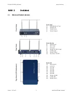
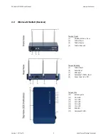
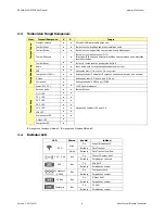
2.3
Buttons & Components functions:
View
Buttons/Components
S
R
Functions
Wireless antenna
z
z
3 Pcs of 2dBi detachable antennas.
Power button
z
z
Switch the button to turn on or off the power supply.
Source button
z
z
Click the button to switch media sources or keep on pushing the button to
switch input media sources continuously.
Front V
iew
Channels button
z
z
Click the button to switch Wi-Fi channels.
Notice: When the transmitter channel is switched the receiver channel will be
switched simultaneously.
Reset button
z
z
Reset This button is for reset to default setting.
Audio
z
z
Audio Connect the audio cable for audio output.
VGA
z
z
Connect the VGA cable to the corresponding VGA port.
Component (YPbPr)
z
z
Connect the Component cables to the corresponding Component connection
ports.
S-Video
z
Connect the S-Video cable to the S-Video port.
Composite
z
Connect the CVBS cable to the CVBS port.
Rear View
Power (12V DC)
z
z
12V DC Connect the power adapter to the power DC port.
Antenna ports
z
z
Detachable antenna to be connected.
Wi-Fi LED
z
z
CH 1 LED
z
z
CH 2 LED
z
z
CH 3 LED
z
z
CH 4 LED
z
z
VGA LED
z
z
Components LED
z
z
S-Video LED
z
Top
V
ie
w
Composite LED
z
Refers to below 2.4 LED Indications Behaviors
‘
S
’ referring to Wireless-N Media S; ‘
R
’ referring to Wireless-N Media R
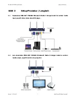
2.4
LED Indications Behaviors
LED Color
Behavior
Indication
On
Wireless function is active
Green
Blinking Data
transmitting
Wi-Fi
Red
Blinking
Data transmitting overflow
On
Wireless channel is active
CH1 ~ CH4
Blue
Blinking Switching
channels
On
VGA source is active
VGA
Blue
Blinking Switching
sources
On
Component source is active
Component
(YPbPr)
Blue
Blinking Switching
sources
On
S-Video source is active
S-Video
Blue
Blinking Switching
sources
On
CV source is active
Composite
Blue
Blinking Switching
sources