ProHD DR-N17F Instruction Manual Download Page 21

21

 Available signals

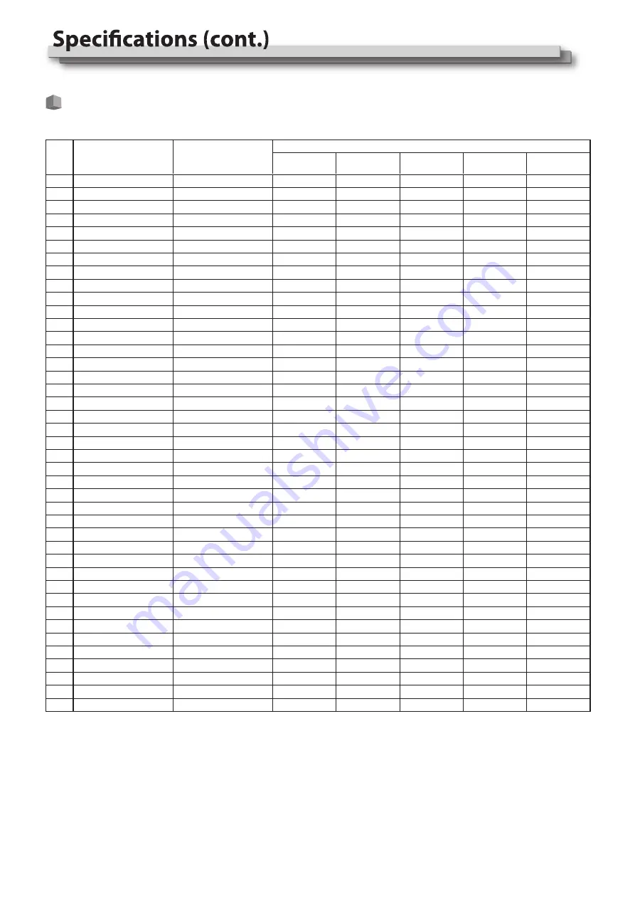
The following signals are available for this monitor.

Video signals

No.

Signal name

1
2
3
4
5
6
7
8
9
10
11
12
13
14
15
16
17
18
19
20
21
22
23
24
25
26
27
28
29
30
31
32
33
34
35
36
37
38
39
40
41

NTSC
NTSC 4.43
PAL-M
PAL
PAL-N
SECAM
480/60i
480/59.94i
576/50i
480/60p
480/59.94p
576/50p
640*480/60p
640*480/59.94p
720/60p
720/59.94p
720/50p
1080/60i
1080/59.94i
1080/50i
1080/60p
1080/59.94p
1080/50p
1080/30p
1080/29.97p
1080/25p
1080/24p
1080/23.98p
1080/30PsF
1080/29.97PsF
1080/25PsF
1080/24PsF
1080/23.98PsF
2048*1080/23.98p
2048*1080/24p
2048*1080/25p
2048*1080/29.97p
2048*1080/30p
2048*1080/50p
2048*1080/59.94p
2048*1080/60p

NTSC
NTSC
PAL
PAL
PAL
SECAM
480i
480i
576i
480p
480p
576p
640*480
640*480
720p60
720p60
720p50
1080i60
1080i60
1080i50
1080p60
1080p60
1080p50
1080p30
1080p30
1080p25
1080p24
1080p24
1080PsF30
1080PsF30
1080PsF25
1080PsF24
1080PsF24
1080p24
1080p24
1080p25
1080p30
1080p30
1080p50
1080p60
1080p60


Signal format shown in 

the status display

Input terminal

CVBS

YPbPr

VGA

SDI

HDMI

√:  Acceptable

—: Not acceptable

      For signal formats other than E.Audio 3G/HD/SD SDI input, **/59.94, **/29.97, and **/23.98 will be displayed as **/60, **/30, and**/24 respectively.

Summary of Contents for DR-N17F

Page 1: ...Version V1 0 0V03 For Customer Use Please read the Instruction Manual carefully and retain this information for future reference MULTI FORMAT LCD MONITOR INSTRUCTIONS DT N17F ...

Page 2: ...in a damp or dusty room where the product is exposed to soot or steam such as near the cooking counter or a humidifier near heat sources where condensation easily occurs such as near the window in a location exposed to direct sunlight or strong light Do not place this product on an unstable cart stand or table The product may fall causing serious injury to a child or adult and serious damage to th...

Page 3: ...ble system Do not overload wall outlets extension cords or convenience or electric shock Slots and openings in the cabinet are provided for ventilation These ensure reliable operation of the product and protect it from overheating These openings must not be blocked or covered Never push objects of any kind into this product through openings as they may touch dangerous voltage points or short circu...

Page 4: ...ontinuous operations of the LCD panel may accelerate the deterioration Operating Precautions IMPORTANT SAFETY INSTRUCTIONS 1 Read these instructions 2 Keep these instructions 3 Heed all warnings 4 Follow all instructions 5 Do not use this apparatus near water 6 Clean only with dry cloth 7 Do not block any ventilation openings Install in accordance with the manufacturer s instructions 8 Do not inst...

Page 5: ...ctions 7 Rear panel 7 Front panel 8 Showing Input Signals 9 Volume Adjustment Audio Channel Selection 9 On the Information Display 9 On the Status Display 9 10 The operation procedure 10 Menu Transition Diagram 10 Main Menu 11 External Control 17 About the external control 17 Using the UMD control 17 Using the GPI control 17 Troubleshooting 18 19 General 19 LCD panel 19 Input output terminals 19 D...

Page 6: ...he LCD panel from being damaged Take out the desktop stand 2 feet from accessory box in the package Clockwise screw the feet onto the bottom of the monitor Do not rest your arm on the monitor or lean against the monitor Do not touch the LCD panel when installing the monitor Be sure to install the monitor securely to prevent the monitor from falling over which may cause damage to the monitor or inj...

Page 7: ...uency of 48 kHz 5 HDMI terminal Input Output terminal for HDMI signals The monitor will not display or output HDMI with HDCP protection page 22 7 AUDIO IN terminals pin jack Input terminals for the analog audio signals Set signal source as ANALOG CVBS VGA YPbPr the analog audio can be monitored as audio meters or output via Speaker Headphone Rear panel Index of Parts and Functionos CAUTION Do not ...

Page 8: ...ress to apply When the menu is inactivated revolve VOLUME MENU PUSH to adjust the sound volume Picture adjustment knob BRIGHT Adjusts the picture brightness and the default value is 50 CONTRAST Adjusts the picture contrast and the default value is 50 SATURATION Adjusts the picture saturation and the default value is 50 Directly press BRIGHT CONTRAST SATURATION knobs the parameters will recover to ...

Page 9: ...ding etc can be changed under Vector submenu User can set function Keys F1 Waveform Press WFM on the front panel to turn on of this function The relevant parameters like WFM position WFM color and WFM blending etc can be changed under Waveform submenu Press VOLUME MENU PUSH button the main menu will pop up from the left top of the screen to display the current working status including 1 Current in...

Page 10: ...le Color Temp Scan Mode Freeze Frame Odd Even Frame F1 F2 F3 F4 F5 System Version Picture Exit Contrast Brightness Sharpness Hue Backlight Color Temp Exit Gamma Color Temp Red Gain Green Gain Blue Gain Red Bias Green Bias Blue Bias Exit F1 F2 F3 F4 F5 GPI Exit GPI Control 1Pin 2Pin 3Pin 4Pin 5Pin 6Pin Source ID Parity Serial Port Baud Rate Display Type RS485 Address Exit UMD Marker Exit Marker Mar...

Page 11: ... Freeze Frame Flip Mode CVBS YPbPr VGA Color Temp Time Code Zebra Vector To do Return Main Menu Assign functions to the function keys F1 F4 on the front key board Item Exit GPI Control 1 1 Pin 2 Pin 3 Pin 4 Pin 5 Pin 6 Pin Setting value Red Tally Green Tally Yellow Tally Aspect Ratio Scan Mode Zoom Mode Mute Freeze Frame Flip Mode Color Temp Time code Zebra Vector Audio Bar Histogram False Color A...

Page 12: ...t Display Type to UMD 3 Set Serial Port to RS485 or RS232 according to the port type of external control equipment 4 Make sure the address Baud Rate Parity the same 5 Adjust the external control equipment and send UMD command the UMD information will be display as the right photo User can set the character and color of the UMD and the color of Tally1 and 2 of actual display screen When Fit Marker ...

Page 13: ...el2 When the current Select Channel is set to Channel1 8 the left channel and right channel output can be selected from Channel1 to channel8 When the current Select Channel is set to Channel1 16 the left channel and right channel output can be selected from Channel1 to channel16 In audio bar the left channel information will be in green and the right channel information will be in red Display sett...

Page 14: ...the background of the waveform display gray High Set the background of the waveform display transparent Waveform color setting Display setting WFM Line Count setting Setting value Setting value Bottom Right Center Top Left Top Right Bottom Left Vector On Vector Position setting Vector Position Vector Blending Color White Green False Color Low High Histogram On Low High Histogram Blending Waveform ...

Page 15: ... Energy Save mode Setting value 16 9 4 3 Normal Off Odd Mode Even Mode Off H Flip V Flip H V Flip Factory User1 User2 User3 OverScan Native Zoom1 Zoom2 Display Waveform Audio Bar Vector Zebra Focus Assist Time Code Histogram False Color AFD H V Delay R G B Mono Color Bar Marker UMD On On On On On On On On On On On On Blue Red Blue Only Red Only Green Only Mono Setting value System Freeze Frame Fli...

Page 16: ...ty operation If the Key Inhibit is On there is no response when all the buttons expert VOLUME MENU PUSH are pressed the sreen will be displayed as Key Inhibit Main Menu Exit Status Picture Color Temp GPI UMD Marker Audio Vector Waveform Display System OSD Key Inhibit Status HDMI XXX User Profile XX Color Temp XXXX Scan Mode XXX Freeze Frame XXX F1 XXX F2 XXX F3 XXX F4 XXX F5 XXX System Version XXX ...

Page 17: ... the order of Normal Overscan Native Off H Llip V Flip H V Flip order of Off Odd Mode Even Mode Zoom1 Zoom2 For every short circuiting the value changes in the order of On For every short circuiting the Color Temp value changes in the order of 6500K 5600K 9300K User Blue Only Red Only Green Only Mono Functions controlled by the GPI terminal Pin No IN terminal signal OUT terminal signal 1 TXD TXD D...

Page 18: ...comes hot The monitor emits a cracking noise The monitor emits a mechanical noise Symptom Probable cause and corrective action press POWER button Firmly insert the AC power plug Select the correct input using the INPUT SELECT buttons Turn on the power of the connected component and set the output correctly Check whether the input signal format is acceptable on the monitor Adjust the volume level D...

Page 19: ...l dimensions excluding protruding parts Weight 4 65 kg 10 25lbs with the stand Accessories AC power cord x 1 17 3 wide active matrix TFT Width 381 89 mm 15 Height 214 81 mm 8 7 16 Diagonal 439 42 mm 17 5 16 LCD panel e p y T e Number of pixels displayed 1920 x 1080 Number of colors displayed 262 144 Viewing angle TYP 160 Horizontally 160 Vertically Brightness TYP 300cd m 2 Contrast ratio TYP 700 1...

Page 20: ... 5 16 15 16 303 8 11 15 16 349 4 13 3 4 310 4 12 1 4 179 2 7 1 16 328 7 12 15 16 100 100 106 135 5 5 16 73 2 7 8 21 13 16 14 9 16 90 70 DT N17F Front view Side view Rear view VESA mounting holes Size M4 depth 10 mm 3 1 2 2 3 4 3 15 16 4 1 8 ...

Page 21: ... 97PsF 1080 25PsF 1080 24PsF 1080 23 98PsF 2048 1080 23 98p 2048 1080 24p 2048 1080 25p 2048 1080 29 97p 2048 1080 30p 2048 1080 50p 2048 1080 59 94p 2048 1080 60p NTSC NTSC PAL PAL PAL SECAM 480i 480i 576i 480p 480p 576p 640 480 640 480 720p60 720p60 720p50 1080i60 1080i60 1080i50 1080p60 1080p60 1080p50 1080p30 1080p30 1080p25 1080p24 1080p24 1080PsF30 1080PsF30 1080PsF25 1080PsF24 1080PsF24 108...

Page 22: ...eld 18 5 V Power 5 T M D S Data 1 shield 12 T M D S Clock 19 Hot Plug Detect 6 T M D S Data 1 13 Spare not connected 7 T M D S Data 0 14 Spare not connected Specification of the mini D SUB15pin terminal Connect it to the mini D SUB15pin output terminal of a video device Notice on transportation This monitor is precision equipment and needs dedicated packing material for transportation Never use an...

Page 23: ...23 MEMO ...

Page 24: ...w swit cc This model is manufactured warranted and supported by SWIT Electronics Co Ltd SWIT Electronics USA LLC and distributed in North America by JVCKENWOOD USA Corporation To obtain service or for further information please contact SWIT Electronics USA LLC Address 3350 Scott Blvd 61 02 Santa Clara CA 95054 Toll free 1 866 986 SWIT 7948 Tel 408 260 8258 Fax 408 228 8438 Email info swit us Websi...

Reviews: