


TTL/PWM - 3Pin Connector for PA-12-T
4. Actuator Control
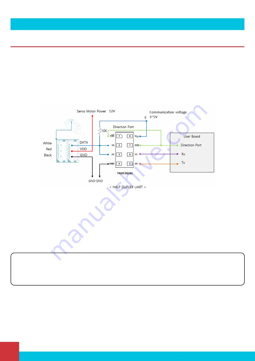
4.1. Circuit Connection
The data structure for communication with the PA-12 on-board microcontroller is half-duplex UART. A full-duplex
communication system allows both devices to transmit and receive data simultaneously. In the case of PA-12, the system
is half-duplex, also known as semi-duplex. This means that the devices can communicate with each other, but not
simultaneously. At any time during communication, one device must transmit while the other one receives, and vice-versa.
For this reason, if you are trying to communicate with a PA-12 through a full-duplex serial COM device, you will need to use
a buffer in between (we recommend implementing a 74LVC2G241 chip).
The direction of the data signal for Tx and Rx of TTL level will be determined according to the level of direction_port as
below.
▪
If the level of "direction_port" is LOW: Rx will receive Data.
▪
If the level of "direction_port" is HIGH: Tx will transmit Data.
Both GNDs between actuator and controller should be connected as above diagram.
▪
For PWM control, connect PWM signal (3~5V) to the Data pin above.
▪
When using PWM communication, position control is possible, but feedback data, such as current position value,
cannot be received, and serial daisy chain connection is not supported since data communication is not supported.
▪
Feedback data reception and daisy chain connections are possible with TTL or RS-485 communication.
P a g e | 10
Progressive Automations – Position Control Communication Protocol


