ProForm PFTL99513.0 User Manual Download Page 22

22

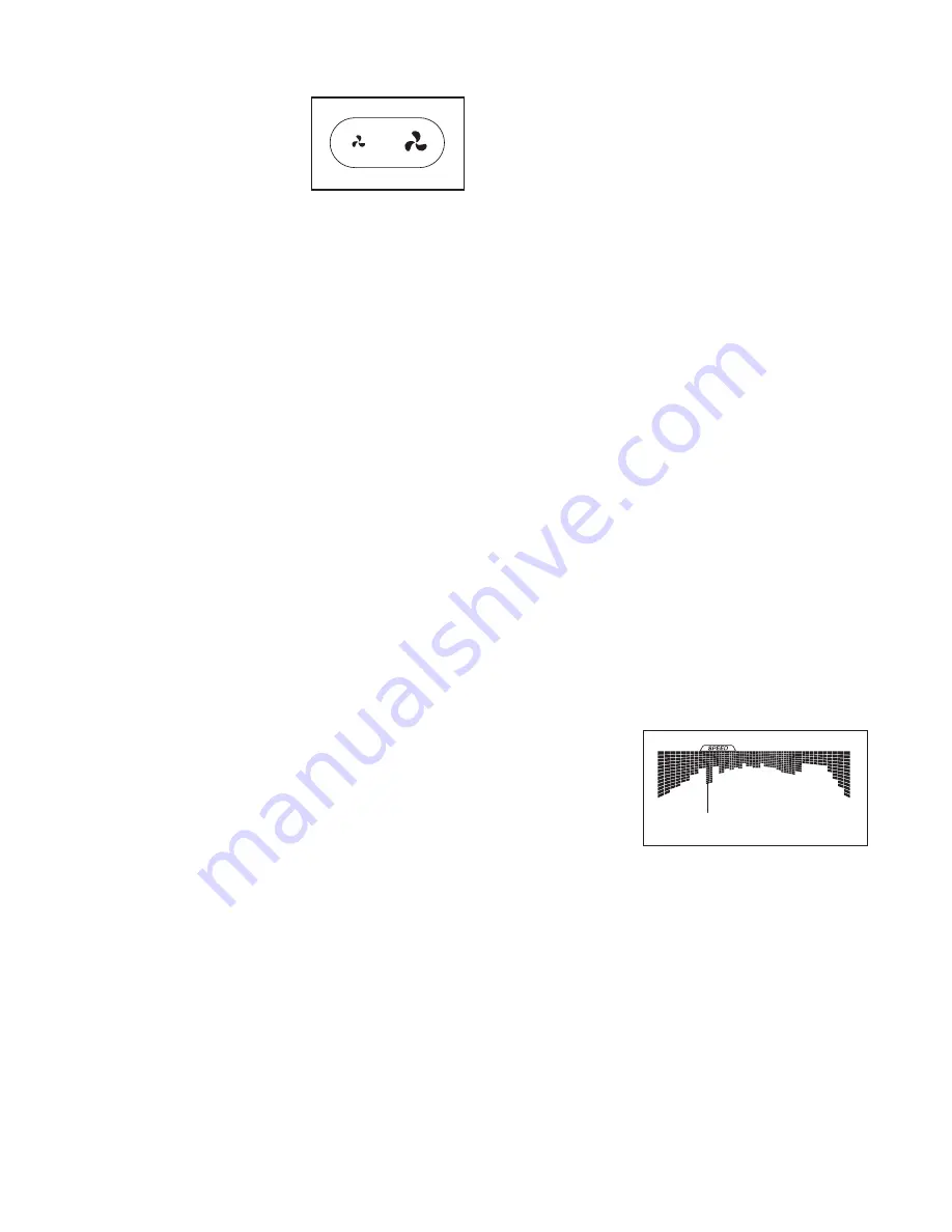
7.  Turn on the fan if desired.


  The fan features multiple 
speed settings. Press 
the fan increase or de-
crease button to select a 
fan speed or to turn off 
the fan. Note: If the fan 
is on when the walking 
belt is stopped, the fan will turn off automatically 
after a few minutes.

8.    When you are finished exercising, remove the 

key from the console.


 Step onto the foot rails, press the Stop button, and 

adjust the incline of the treadmill to zero.


The 

incline must be zero or you may damage the 
treadmill when you fold it to the storage posi-
tion. 

Next, remove the key from the console and 

put it in a secure place.  


 When you are finished using the treadmill, press 
the power switch into the off position and unplug 
the power cord. 

IMPORTANT: If you do not do 

this, the treadmill’s electrical components may 
wear prematurely. 

HOW TO USE AN ONBOARD WORKOUT

1.    Insert the key into the console. 


 See HOW TO TURN ON THE POWER on page 20. 

2.  Select an onboard workout.


 To select an onboard workout, press the Speed 
button, the Incline button, the Intensity button, 
or the Calorie button repeatedly until the desired 
workout appears in the display.


 When you select an onboard workout, the displays 
will show the maximum incline, the duration, the 
distance, the maximum speed, and the name of the 
workout. In addition, a pro

 le of the speed settings 

of the workout will appear in the matrix. If you se-
lect a calorie workout, the approximate number of 
calories you will burn will appear in the name of the 
workout.

3.  Start the workout.


 Press the Start button or the Speed increase button 
to start the workout. A moment after you press the 
button, the treadmill will automatically adjust to the 
first speed and incline settings of the workout. Hold 
the handrails and begin walking. 


Each workout is divided into segments. One speed 
setting and one incline setting are programmed for 
each segment. Note: The same speed setting and/
or incline setting may be programmed for consecu-
tive segments. 


 During the 
workout, the 
pro

 le will 

show your 
progress. 
The 

 ash-

ing segment 
of the pro

 le 

represents the current segment of the workout. The 
height of the 

 ashing segment indicates the ap-

proximate speed setting for the current segment. 
At the end of each segment, a series of tones will 
sound and the next segment of the pro

 le will begin 

to 

 ash. If a new speed and/or incline setting is 

programmed for the next segment, the new speed 
and/or incline setting will appear in the displays for 
a few seconds and the treadmill will automatically 
adjust to the new speed and/or incline setting.


Current Segment

Summary of Contents for PFTL99513.0

Page 1: ...using this equipment Save this manual for future reference USER S MANUAL www proform com ACTIVATE YOUR WARRANTY To register your product and activate your warranty today go to www proformservice com r...

Page 2: ...ls may not be shown at actual size WARNING DECAL PLACEMENT PROFORM is a registered trademark of ICON IP Inc WARNING DECAL PLACEMENT 2 IMPORTANT PRECAUTIONS 3 BEFORE YOU BEGIN 7 PART IDENTIFICATION CHA...

Page 3: ...es sor into an appropriate outlet see page 18 To avoid overloading the circuit do not plug other electrical devices except for low power devices such as cell phone chargers into the surge suppressor o...

Page 4: ...45 lbs 20 kg to raise lower or move the treadmill 23 When folding or moving the treadmill make sure that the storage latch is holding the frame securely in the storage position 24 Never insert any ob...

Page 5: ...5...

Page 6: ...6 all STANDARD SERVICE PLANS...

Page 7: ...If you have questions after reading this manual please see the front cover of this manual To help us assist you please note the product model number and serial number before contacting us The model nu...

Page 8: ...Screw 28 4 Wheel Spacer 63 2 PART IDENTIFICATION CHART Use the drawings below to identify small parts used for assembly The number in parentheses below each draw ing is the key number of the part from...

Page 9: ...marked L or Left and right parts are marked R or Right To identify small parts see page 8 Assembly requires the following tools the included hex key one adjustable wrench one Phillips screwdriver To...

Page 10: ...und the end of the Upright Wire 81 Then insert the Upright Wire into the lower end of the Right Upright as you pull the other end of the wire tie out of the Right Upright Then remove and discard the i...

Page 11: ...nder the right side of the Base 94 Hold the Right Upright 90 against the Base Make sure not to pinch the Upright Wire 81 Insert two 3 8 x 4 Screws 7 with two 3 8 Star Washers 13 into the Right Upright...

Page 12: ...rs 84 85 Slide the Left Bottom Handrail Cover onto the Left Upright 89 and slide the Right Bottom Handrail Cover onto the Right Upright 90 82 85 90 83 84 89 7 Attach the Left Handrail 86 to the Left U...

Page 13: ...ve the four 5 16 x 1 2 Screws 4 They will be used in the next step 8 9 C 4 C 4 Console Assembly 10 Set the console assembly on the Left and Right Handrails 86 87 Make sure not to pinch any wires D 81...

Page 14: ...Upright Wire 81 to the console wire D See the inset drawing The connec tors should slide together easily and snap into place If they do not turn one connector and try again IF YOU DO NOT CONNECT THE...

Page 15: ...Left Handrail Cover 79 to the Left Handrail 86 in the same way 92 79 86 1 87 1 13 14 Slide the Left Bottom Handrail Cover 85 up against the Left Handrail Cover 79 and attach the Left Bottom Handrail C...

Page 16: ...ker E is facing the treadmill Attach the Latch Crossbar to the brackets on the Frame 56 with two 5 16 x 3 4 Screws 25 and two 5 16 Star Washers 11 56 38 E 11 11 25 25 Brackets 15 16 Orient the Storage...

Page 17: ...Cover 82 and the Right Base Cover 83 onto the Base 94 18 83 82 94 7 19 Make sure that all parts are properly tightened before you use the treadmill If there are sheets of plastic on the treadmill deca...

Page 18: ...into a surge suppressor and plug the surge suppressor into an appropriate outlet that is properly installed and grounded in accordance with all local codes and ordinances The outlet must be on a nomi...

Page 19: ...our wireless network With the iFit mode you can download per sonalized workouts create your own workouts track your workout results race against other iFit users and access many other features You can...

Page 20: ...THE MANUAL MODE 1 Insert the key into the console See HOW TO TURN ON THE POWER at the left 2 Select the manual mode Press the Manual button on the console If you are not connected to iFit the manual...

Page 21: ...progress The My Trail tab will also show the number of laps you complete The Calorie tab will show the approximate amount of calories you have burned The height of each segment represents the amount o...

Page 22: ...ow the maximum incline the duration the distance the maximum speed and the name of the workout In addition a pro le of the speed settings of the workout will appear in the matrix If you se lect a calo...

Page 23: ...on the fan if desired See step 7 on page 22 7 When you are finished exercising remove the key from the console See step 8 on page 22 HOW TO USE A SET A GOAL WORKOUT 1 Insert the key into the console...

Page 24: ...t the display will show the duration of the workout the distance you will walk or run and the approximate number of calories you will burn The display may also show the name of the workout 5 Start the...

Page 25: ...ow the instructions shown in the lower part of the display 3 Change settings as desired Demo The console features a display demo mode designed to be used if the treadmill is dis played in a store Whil...

Page 26: ...network Then press the Enter button Note Do not select IFIT_SETUP Note The time display will show the number of the currently selected access point The distance display will show the total number of a...

Page 27: ...e is within range of the console and then close and re open your list of networks Also see Clear WiFi Setting on page 26 and clear any previous wireless network settings on the console Note The networ...

Page 28: ...mill Keep the treadmill out of direct sunlight Do not leave the treadmill in the storage position in temperatures above 85 F 30 C HOW TO MOVE THE TREADMILL Before moving the treadmill fold it as descr...

Page 29: ...PTOM The power turns off during use a Check the power switch see the drawing above If the switch has tripped wait for ve minutes and then press the switch back in b Make sure that the power cord is pl...

Page 30: ...brated remove the key from the console SYMPTOM The walking belt slows when walked on a Use only a surge suppressor that meets all of the speci cations described on page 18 b If the walking belt is ove...

Page 31: ...sing the hex key turn both idler roller screws clockwise 1 4 of a turn When the walk ing belt is correctly tightened you should be able to lift each edge of the walking belt 2 to 3 in 5 to 7 cm off th...

Page 32: ...c Exercise If your goal is to strengthen your cardiovascular system you must perform aerobic exercise which is activity that requires large amounts of oxygen for prolonged periods of time For aerobic...

Page 33: ...lles Stretch With one leg in front of the other reach forward and place your hands against a wall Keep your back leg straight and your back foot flat on the floor Bend your front leg lean forward and...

Page 34: ...Caution Decal 44 1 Walking Platform 45 1 Walking Belt 46 2 Belt Guide 47 1 Right Rear Foot 48 4 Cable Tie 49 1 Drive Roller Pulley 50 1 Magnet 51 1 Reed Switch Clip 52 1 Reed Switch 53 1 Storage Latc...

Page 35: ...Star Washer 107 2 8 x 1 3 4 Screw 108 6 8 x 3 4 Washer Head Screw 109 2 Base Pad 110 1 Left Foot Pad 111 1 Right Foot Pad 112 1 Left Front Cushion Top 113 1 Right Front Cushion Top User s Manual Note...

Page 36: ...19 50 14 51 21 106 45 102 10 10 48 23 15 34 30 59 61 15 30 34 59 23 19 46 43 42 44 21 34 30 59 24 24 57 100 100 102 24 2 2 103 104 2 24 108 25 11 39 35 35 2 14 113 26 2 14 39 35 2 112 39 14 35 2 26 39...

Page 37: ...37 68 66 65 102 102 102 68 10 76 77 40 40 2 68 75 99 2 2 73 72 2 2 2 2 78 24 24 24 68 68 2 67 67 33 29 69 33 70 16 71 33 33 71 32 EXPLODED DRAWING B Model No PFTL99513 0 R0214A...

Page 38: ...7 81 94 22 22 10 82 91 7 83 89 90 91 13 63 62 74 7 13 74 62 63 81 1 11 92 86 11 4 79 87 1 1 1 1 1 1 1 1 4 11 28 11 28 84 85 1 17 17 33 33 97 97 109 14 14 109 EXPLODED DRAWING C Model No PFTL99513 0 R0...

Page 39: ...39 8 1 2 18 41 41 10 58 1 1 1 2 1 2 1 96 96 5 9 11 1 5 1 1 1 1 1 1 1 64 2 99 1 1 1 1 1 80 36 27 1 1 88 95 93 9 31 37 98 2 2 101 2 EXPLODED DRAWING D Model No PFTL99513 0 R0214A...

Page 40: ...et forth above is authorized by ICON ICON is not responsible or liable for indirect special or consequential damages arising out of or in con nection with the use or performance of the product damages...

Reviews: