background image

18

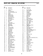
PART LISTÑModel No. 831.297982

R0399A

1

2

Center Track

2

2

Foot Rail

3

1

Left Foot Rail Cap

4

1

Front Roller Adjustment Nut

5

4

Isolator

6

6 Bumper

7

6

Platform Screw

8

1

Walking Platform

9

2

Frame Pivot Bolt

10

2

Frame Pivot Spacer

11

1

Walking Belt

12

1

Front Roller/Pulley

13

12

Small Screw

14

1

Motor Belt

15

1

Base

16

1

Incline Frame

17

2

Hood Bracket (long)

18

3

Bracket Clip

19

4

Small Screw

20

1

Console Plate

21

8

Nut

22

1

Lift Motor Shield

23

2

Incline Motor Bolt

24

1

Allen Wrench

25

1

Incline Motor

26

1

Reed Switch

27

1

Upright Plug

28

1

Rail Cap Screw

29

1

Adhesive Clip

30

2

Wheel Bolt

31

2

Front Wheel

32

1

Hood Bracket (short)

33

1

Motor Pivot Nut

34

1

Pulley/Flywheel/Fan

35

1

Motor

36

3

Motor Tension Bolt

37

1

Motor Tension Washer

38

1

Star Washer

39

1

Motor Tension Nut

40

1

Motor Pivot Bolt

41

1

Motor Hood

42

1

Incline Motor Shield

43

2

Incline Pivot Washer

44

3

Adj. Washer

45*

1

Motor/Pulley/Fly./Fan

46

1

Front Roller Adj. Bolt

47

1

Choke

48

1

Electronics Bracket

49

1

Controller

50

1

Electronics Shield

51

1

Power Supply

52

4

Plastic Stand-off

53

1

Power Cord

54

1

Grommet

55

1

On/Off Switch

56

1

Circuit Breaker

57

1

Outlet Bracket

58

1

Book Rack

59

2

Belt Guide

60

1

Shock

61

1

Front Belly Pan

62

1

Right Foot Rail Cap

63

26

Belly Pan Fastener

64

1

Console Base

65

2

Frame Guide Screw

66

1

Frame Guide

67

2

Rear Isolator

68

1

Belly Pan

69

1

Upright Wire Harness

70

4

Hood Screw

71

1

Key/Clip

72

2

Rear Endcap Bracket

73

1

Rear Endcap

74

2

Rear Endcap Pad

75

7

Endcap Screw/Ground Screw

76

2

Rear Roller Adj. Bolt

77

2

Caution Decal

78

1

Latch Decal

79

1

Frame

80

2

Rear Deck Screw

81

1

Console

82

1

Latch Catch

83

1

Rear Roller

84**

1

Optional Hand Weight/Chest Pulse

85

1

Cable Tie

86

2

Cable Tie Screw

87

2

Cable Tie Clamp

88

2

8Ó Cable Tie

89

5

4Ó Cable Tie

90

1

Upright Wire Harness

91

2

Handrail Grip

92

1

Lock Knob

93

1

Lock Knob Sleeve

94

1

Spring

95

1

Lock Pin Collar

96

1

Pin Clip

97

1

Lock Pin

98

1

8Ó Wire Harness

99

4

Pulse Sensor Plate

100

1

Ground Wire

Key

No. Qty.

Description

Key

No. Qty.

Description

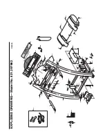
To identify parts listed below, refer to the EXPLODED DRAWING attached in the center of this manual.

Summary of Contents for 831.297982

Page 1: ...ual before using this equipment Save this manual for future reference Serial Number Decal Model No 831 297982 Serial No Find the serial number in the location shown below Write the serial number in the space above for reference SEARS ROEBUCK AND CO HOFFMAN ESTATES IL 60179 ...

Page 2: ...ERATION AND ADJUSTMENT 7 HOW TO FOLD AND MOVE THE TREADMILL 12 MAINTENANCE AND TROUBLE SHOOTING 14 CONDITIONING GUIDELINES 16 PART LIST 18 ORDERING REPLACEMENT PARTS Back Cover FULL 90 DAY WARRANTY Back Cover Note An EXPLODED DRAWING is attached in the center of this manual 2 ...

Page 3: ...voltage rating of 400 volts or less and a minimum surge dis sipation of 450 joules The surge suppressor must be electrically rated for 120 volts AC and 15 amps 12 Keep the power cord and the surge suppres sor away from heated surfaces 13 Never move the walking belt while the power is turned off Do not operate the treadmill if the power cord or plug is damaged or if the treadmill is not working pro...

Page 4: ...d for in home use only Do not use this treadmill in any commer cial rental or institutional setting WARNING Before beginning this or any exercise program consult your physician This is especially important for persons over the age of 35 or persons with pre existing health problems Read all instructions before using SEARS assumes no responsibility for personal injury or property damage sustained by...

Page 5: ...p us assist you please note the product model number and serial num ber before calling The model number of the treadmill is 831 297982 The serial number can be found on a decal attached to the treadmill see the front cover of this manual for the location Before reading further please review the drawing below and familiarize yourself with the parts that are labeled BEFORE YOU BEGIN Handrail Hand We...

Page 6: ...h a soft cloth and a mild non abrasive cleaner 1 With the help of a second person carefully raise the Uprights 15 until the treadmill is in the position shown 2 Next make sure the Lock Knob Sleeve 93 is fully in serted into the left Upright 15 Remove the Lock Knob 92 from the Lock Pin 97 Make sure that the Lock Pin Collar 95 and the Spring 94 are on the Lock Pin Insert the Lock Pin into the left U...

Page 7: ...ductor and a grounding plug Plug the power cord into a surge suppressor and plug the surge suppressor into an appropriate outlet that is properly installed and grounded in accordance with all local codes and ordinances This product is for use on a nominal 120 volt circuit and has a grounding plug that looks like the plug illus trated in drawing 1 below A temporary adapter that looks like the adapt...

Page 8: ...ke sure that the on off switch lo cated near the power cord is in the on posi tion Next plug in the power cord see HOW TO PLUG IN THE POWER CORD on page 7 Note If the key is in the console remove it before plugging in the power cord Step onto the foot rails of the treadmill Find the clip attached to the key see the drawing above and slide the clip onto the waistband of your clothing Follow the ste...

Page 9: ...ime until you have com pleted 1 4 mile A new lap will then begin DISTANCE LAPS displayÑThis display shows the distance that the walking belt has moved and the number of 1 4 mile laps you have completed The display will alternate between one number and the other every seven seconds the indicator will light when the number of laps is shown TIME INCLINE displayÑThis display shows the elapsed time and...

Page 10: ...will gradually increase during the first ten minutes and then gradually decrease during the last ten minutes Each program begins with a warm up period and ends with a cool down period Set a maximum incline or speed setting If you selected an incline program a number will flash in the TIME INCLINE display This number is the maxi mum incline that the treadmill will reach during the selected program ...

Page 11: ...flash in the SPEED PACE display This number is the maximum speed that the treadmill will reach during the program Press the SPEED or button repeatedly to change the maximum speed setting If the setting is increased the diffi culty level of the entire program will increase if the setting is decreased the difficulty level of the entire program will decrease To stop the program for a moment press the...

Page 12: ...power cord CAU TION You must be able to safely lift 45 pounds 20 kg in order to raise lower or move the treadmill 1 Hold the treadmill with your hands in the locations shown at the right CAUTION To decrease the possibility of injury bend your legs and keep your back straight As you raise the treadmill make sure to lift with your legs rather than your back Raise the treadmill about halfway to the v...

Page 13: ...injury use extreme caution while moving the treadmill Do not attempt to move the treadmill over an uneven surface 3 Place one foot on the base and carefully lower the treadmill until it is resting in the storage position HOW TO LOWER THE TREADMILL FOR USE 1 Hold the upper end of the treadmill with your right hand as shown Using your left hand pull the latch knob to the left and hold it Pivot the t...

Page 14: ...er wait for five minutes and then press the switch back in d Check the on off switch located on the treadmill near the power cord The switch must be in the on position 2 SYMPTOM THE POWER TURNS OFF DURING USE a Check the circuit breaker located on the treadmill frame near the power cord see 1 c above If the circuit breaker has tripped wait for five minutes and then press the switch back in b Make ...

Page 15: ... the walking belt still slows when walked on please call our toll free HELPLINE 6 SYMPTOM The walking belt is off center a If the walking belt has shifted to the left first remove the key and UNPLUG THE POWER CORD Using the allen wrench turn the left rear roller adjustment bolt clockwise and the right bolt coun terclockwise 1 4 of a turn each Be careful not to overtighten the walking belt Plug in ...

Page 16: ...your goal is to strengthen your cardiovascular sys tem your exercise must be Òaerobic Ó Aerobic exercise is activity that requires large amounts of oxygen for prolonged periods of time This increases the demand on the heart to pump blood to the muscles and on the lungs to oxygenate the blood For aerobic exercise adjust the speed and incline of the treadmill until your heart rate is near the highes...

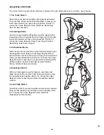
Page 17: ...chilles Stretch With one leg in front of the other reach forward and place your hands against a wall Keep your back leg straight and your back foot flat on the floor Bend your front leg lean forward and move your hips toward the wall Hold for 15 counts then relax Repeat 3 times for each leg To cause further stretching of the achilles tendons bend your back leg as well Stretches Calves achilles ten...

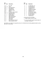
Page 18: ...lectronics Bracket 49 1 Controller 50 1 Electronics Shield 51 1 Power Supply 52 4 Plastic Stand off 53 1 Power Cord 54 1 Grommet 55 1 On Off Switch 56 1 Circuit Breaker 57 1 Outlet Bracket 58 1 Book Rack 59 2 Belt Guide 60 1 Shock 61 1 Front Belly Pan 62 1 Right Foot Rail Cap 63 26 Belly Pan Fastener 64 1 Console Base 65 2 Frame Guide Screw 66 1 Frame Guide 67 2 Rear Isolator 68 1 Belly Pan 69 1 U...

Page 19: ...k 117 1 Short Incline Motor Spacer 118 1 Wire Harness Grommet 1 14Ó White Wire 2 F 1 8Ó White Wire M F 1 4Ó White Wire M F 1 4Ó Black Wire 2 F 1 4Ó Black Wire M Ring 1 9Ó Black Wire M F 1 8Ó Blue Wire 2 F 1 8Ó Green Wire F Ring 1 55Ó Pulse Wire Harness 1 40Ó Wire Harness 1 23Ó Wire Harness 1 User s Manual These parts are not illustrated Includes all parts shown in the box For more information abou...

Page 20: ... 21 14 7 36 37 38 39 33 40 10 36 34 21 17 13 18 16 21 13 13 18 21 44 46 80 35 109 56 53 54 57 109 109 48 109 47 80 7 7 49 59 69 19 72 19 72 75 100 83 45 51 52 52 55 21 1 3 28 28 62 1 65 5 18 32 17 4 5 65 13 110 26 107 50 63 63 111 111 65 66 36 108 21 25 114 115 116 112 113 EXPLODED DRAWINGÑModel No 831 297982 R0399A ...

Page 21: ...87 89 13 42 71 88 30 21 31 6 75 70 70 69 106 31 70 118 105 28 104 103 99 99 99 99 101 103 104 102 102 102 102 81 64 102 102 102 13 13 6 75 105 6 75 13 22 105 105 75 6 75 6 58 84 15 20 27 98 92 93 94 95 96 97 77 77 EXPLODED DRAWINGÑModel No 831 297982 R0399A ...

Page 22: ...nual Model No 831 297982 QUESTIONS If you find that you need help assembling or operating the PROFORM J8 treadmill a part is missing or you need to schedule repair service call our toll free HELPLINE 1 800 736 6879 MondayÐSaturday 7 amÐ7 pm Central Time excluding holidays REPLACEMENT PARTS If parts become worn and need to be replaced call the following toll free number 1 800 FON PART 1 800 366 727...

Reviews: