background image

13

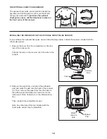
HOW TO USE A SMART PROGRAM

1. Begin pedaling to turn on the console.

See step 1 on page 11.

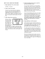
2. Select a smart program.

To select one of the
eight smart pro-
grams, press the
Personal Trainer
Programs button
repeatedly until the
name of the
desired program
appears in the display. The program time and a
profile of the resistance levels for the program will
also appear in the display.

3. Begin pedaling to start the program.

Each program is divided into 20 or 30 one-minute
segments. One resistance level and one target
pace setting are programmed for each segment.
Note: The same resistance level and/or target pace
setting may be programmed for two or more con-
secutive segments. 

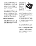
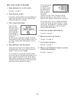
The program profile will show your progress (see
the drawing above). The flashing segment of the
profile represents the current segment of the pro-
gram. The height of the flashing segment indicates
the resistance level for the current segment.

When the first segment of the program ends, the
resistance level and the target pace for the second
segment will appear in the center of the display for
a few seconds to alert you. The next segment of
the profile will begin to flash, and the pedals will
automatically adjust to the resistance level for the
next segment. 

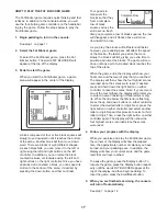
As you exercise,
you will be prompt-
ed to keep your
pedaling pace near
the target pace set-
ting for the current
segment. When an
upward arrow appears in the display, increase
your pace. When a downward arrow appears,
decrease your pace. When no arrow appears,
maintain your current pace.

Important: The target pace settings are intend-
ed only to provide motivation. Your actual pace
may be slower than the target pace settings.
Make sure to pedal at a pace that is comfort-
able for you. 

If the resistance level for the current segment is
too high or too low, you can manually override the
setting by pressing the Quick Resistance buttons.
Important: When the current segment of the
program ends, the pedals will automatically
adjust to the resistance level for the next seg-
ment.

The program will continue in this way until the last
segment ends. To stop the program at any time,
stop pedaling. A tone will sound and the time will
begin to flash in the display. To restart the program,
simply resume pedaling. To reset the program,
press the Start/Reset button.

4. Follow your progress with the display.

See step 4 on page 11.

5. Measure your heart rate if desired.

See step 5 on page 12.

6. Turn on the fan if desired.

See step 6 on page 12.

7. When you are finished exercising, the console

will turn off automatically.

See step 7 on page 12.

Profile

Summary of Contents for 780 Ekg Bike

Page 1: ...ce www iconeurope com Visit our website at USER S MANUAL QUESTIONS As a manufacturer we are commit ted to providing complete customer satisfaction If you have questions or if there are missing parts please contact us at the numbers or addresses listed below Call 08457 089 009 Outside UK 0 44 113 3877133 Fax 0 44 113 3877125 E mail csuk iconeurope com Write ICON Health Fitness Ltd Unit 4 Revie Road...

Page 2: ...ODED DRAWING 23 ORDERING REPLACEMENT PARTS Back Cover PROFORM is a registered trademark of ICON IP Inc WARNING DECAL PLACEMENT The warning decal shown here has been applied in the location shown If a decal is missing or illegible call the telephone num ber on the front cover of this manual and request a free replacement decal Apply the decal in the location shown Note The decal may not be shown at...

Page 3: ...rts regular ly Replace any worn parts immediately 8 Keep children under the age of 12 and pets away from the exercise cycle at all times 9 Wear appropriate clothes while exercising do not wear loose clothes that could become caught on the exercise cycle Always wear athletic shoes for foot protection 10 The exercise cycle should not be used by persons weighing more than 113 kg 250 lbs 11 The pulse ...

Page 4: ...al carefully before using the treadmill If you have questions after read ing this manual please see the front cover of this manual To help us assist you note the product model number and serial number before contacting us The model number and the location of the serial number decal are shown on the front cover of this manual Before reading further please familiarize yourself with the parts labeled...

Page 5: ...awing is the key number of the part from the PART LIST near the end of this manual The number following the parentheses is the quantity used in assembly Note Some small parts may have been pre assembled for shipping If a part is not in the parts bag check to see if it has been preassembled M10 x 85mm Button Screw 23 4 M10 x 50mm Button Screw 48 3 M6 x 10mm Screw 46 2 M4 x 19mm Screw 47 2 M10 Split...

Page 6: ... of the Handlebar Post and slide the Handlebar Post onto the Frame Be careful not to pinch the Wire Harnesses Attach the Handlebar Post 6 to the Frame 1 with three M10 x 50mm Button Screws 48 and three M10 Split Washers 55 tighten the two Button Screws in the front of the Handlebar Post first and then tighten the third Button Screw 1 23 3 3 55 55 55 48 48 1 51 Avoid pinching the wire har nesses du...

Page 7: ...a second person holds the Handlebar 7 near the Handlebar Post 6 insert the Left and Right Controller Wires 59 60 into the hole in the Handlebar Post and upward out of the top of the Handlebar Post Attach the Handlebar 7 to the Handlebar Post 6 with the Handlebar Clamp 22 and the Adjustment Handle 10 Note The Adjustment Handle works like a spanner Turn the Adjustment Handle clock wise pull it away ...

Page 8: ... 31 8 7 9 Identify the Left Pedal 24 which is marked with a Left sticker Using an adjustable wrench firmly tighten the Left Pedal counterclockwise into the Left Crank Arm 15 Tighten the Right Pedal not shown clockwise into the Right Crank Arm not shown Important Tighten both Pedals as firmly as possible After using the exercise cycle for one week retighten the Pedals For best perfor mance keep the...

Page 9: ...ghten it HOW TO ADJUST THE LATERAL POSITION OF THE SEAT To adjust the lateral position of the seat first loosen the seat knob a few turns Then move the seat forward or backward to the desired posi tion and firmly tight en the seat knob HOW TO ADJUST THE PEDAL STRAPS To adjust the pedal straps press the tabs on the sides of the pedals and adjust the pedal straps to the desired position HOW TO ADJUS...

Page 10: ...utomatically control the resistance of the pedals and prompt you to maintain a constant pedaling pace to keep your heart rate near target heart rate settings dur ing your workouts You can also select a watts program that changes the resistance of the pedals to keep your power output near a target level In addition the console features two motivational inter active games Using the dual game control...

Page 11: ...ected resistance level 4 Follow your progress with the display The upper left corner of the display will show the elapsed time Note When a program is select ed with the exception of the watts program the display will show the time remaining in the program instead of the elapsed time The lower left corner of the display will show the distance you have pedaled in miles or kilome ters and your power ...

Page 12: ... at the same time the console will not dis play your heart rate accurately If there are sheets of clear plastic on the metal contacts on the handgrip pulse sensor remove the plas tic To measure your heart rate hold the handgrip pulse sensor with your palms resting against the metal contacts Avoid moving your hands or gripping the contacts too tightly When your pulse is detected one two or three da...

Page 13: ...ally adjust to the resistance level for the next segment As you exercise you will be prompt ed to keep your pedaling pace near the target pace set ting for the current segment When an upward arrow appears in the display increase your pace When a downward arrow appears decrease your pace When no arrow appears maintain your current pace Important The target pace settings are intend ed only to provid...

Page 14: ...If you hold the handgrip pulse sensor and wear the chest pulse sensor at the same time the console will not display your heart rate accurately If you use the handgrip pulse sensor it is not nec essary to hold the handgrip pulse sensor continu ously during a heart rate program however you should hold the handgrip pulse sensor frequently for the program to operate properly Each time you hold the han...

Page 15: ...de the resistance levels however you might not maintain the target heart rate Also when the console compares your heart rate to the target heart rate setting the resistance of the pedals may automatically increase or decrease to bring your heart rate closer to the target heart rate setting The program will continue in this way until the last segment ends To stop the program at any time stop pedali...

Page 16: ...your power output to the target watts setting If your power output is too far below or above the target watts setting the resistance of the pedals will auto matically increase or decrease to bring your power output closer to the target watts setting During the program you will also be prompted to pedal at a steady pace When an upward arrow appears in the display increase your pace When a downward ...

Page 17: ...t the speed of the blocks the faster you pedal the more slowly the blocks will fall giving you extra time to position and orient the blocks The game will con tinue until any part of a stacked block reaches the top of the arena When the game ends the display will show your final score and the level of play that you reached The display will then show the four highest scores recorded since the scores...

Page 18: ...er is hit it will be disabled and another laser blaster will appear in its place there are a total of four laser blasters If you vaporize the entire squadron of drones a new squadron will appear As you play the drones will move faster and faster The game will continue until all four laser blasters are disabled or a drone reaches the bot tom of the arena When the game ends the display will show the...

Page 19: ...iver included with the chest pulse sensor 1 Remove the cover from the compartment on the bot tom of the Console 9 Connect the wire on the receiver A to the wire in the console 9 A Cover Console Wire 9 A Adhesive Pad Attach receiver here 2 Remove the paper from one side of the adhesive pad and press the pad onto the back of the receiver A Then remove the paper from the other side of the adhesive pa...

Page 20: ...r floor turn one or both of the leveling feet beneath the rear sta bilizer until the exer cise cycle is level HOW TO ADJUST THE BELT If you can feel the pedals slip while you are pedaling even when the resistance is at the highest level the belt may need to be adjusted To adjust the belt first remove all the screws from the left and right side shields Then carefully pull the side shields apart Nex...

Page 21: ...iovascular sys tem your exercise must be aerobic Aerobic exer cise is activity that requires large amounts of oxygen for prolonged periods of time This increases the demand on the heart to pump blood to the muscles and on the lungs to oxygenate the blood For aerobic exercise adjust the intensity of your exercise until your heart rate is near the highest number in your training zone WORKOUT GUIDELI...

Page 22: ...ontroller 42 2 Stabilizer Endcap 43 3 M8 Nylon Jamnut 44 4 M8 Split Washer 45 2 5 16 x 1 Flange Screw 46 2 M6 x 10mm Screw 47 2 M4 x 19mm Screw 48 3 M10 x 50mm Button Screw 49 4 M8 Nylon Locknut 50 1 Lower Wire Harness 51 1 Upper Wire Harness 52 4 M6 x 16mm Screw 53 4 M6 Nylon Locknut 54 20 M4 x 16mm Screw 55 3 M10 Split Washer 56 1 Idler Spacer 57 1 Idler Nut 58 2 Grip Screw 59 1 Left Controller ...

Page 23: ... 38 21 53 46 54 54 54 47 55 48 55 48 23 54 54 45 26 54 54 23 32 21 43 36 49 44 44 54 45 26 54 25 24 27 28 55 50 51 17 43 35 35 33 52 37 37 40 40 10 22 30 54 54 41 30 66 54 54 66 66 62 64 63 61 67 56 68 43 57 59 65 58 65 58 60 71 70 69 72 23 EXPLODED DRAWING Model No PFEVEX4916 1 R0707A ...

Page 24: ...To help us assist you be prepared to provide the following information when contacting us the model number and the serial number of the product see the front cover of this manual the name of the product see the front cover of this manual the key number and description of the part s see the PARTS LIST and the EXPLODED DRAWING near the end of this manual ...

Reviews: