


2-9
Installing and Connecting the External Power Supply Shelf
Installation Procedures
In
st
all
ing
and Con
nect
ing
the
Exte
rna
l
Po
wer
Su
ppl
y Sh
elf
4. Connect the Power Supply Shelf to a Switch
Connect the EPS cables from the supported network switches to the appro-
priate ports on the Power Supply Shelf. Also see “Recommended Connection
Topologies” on
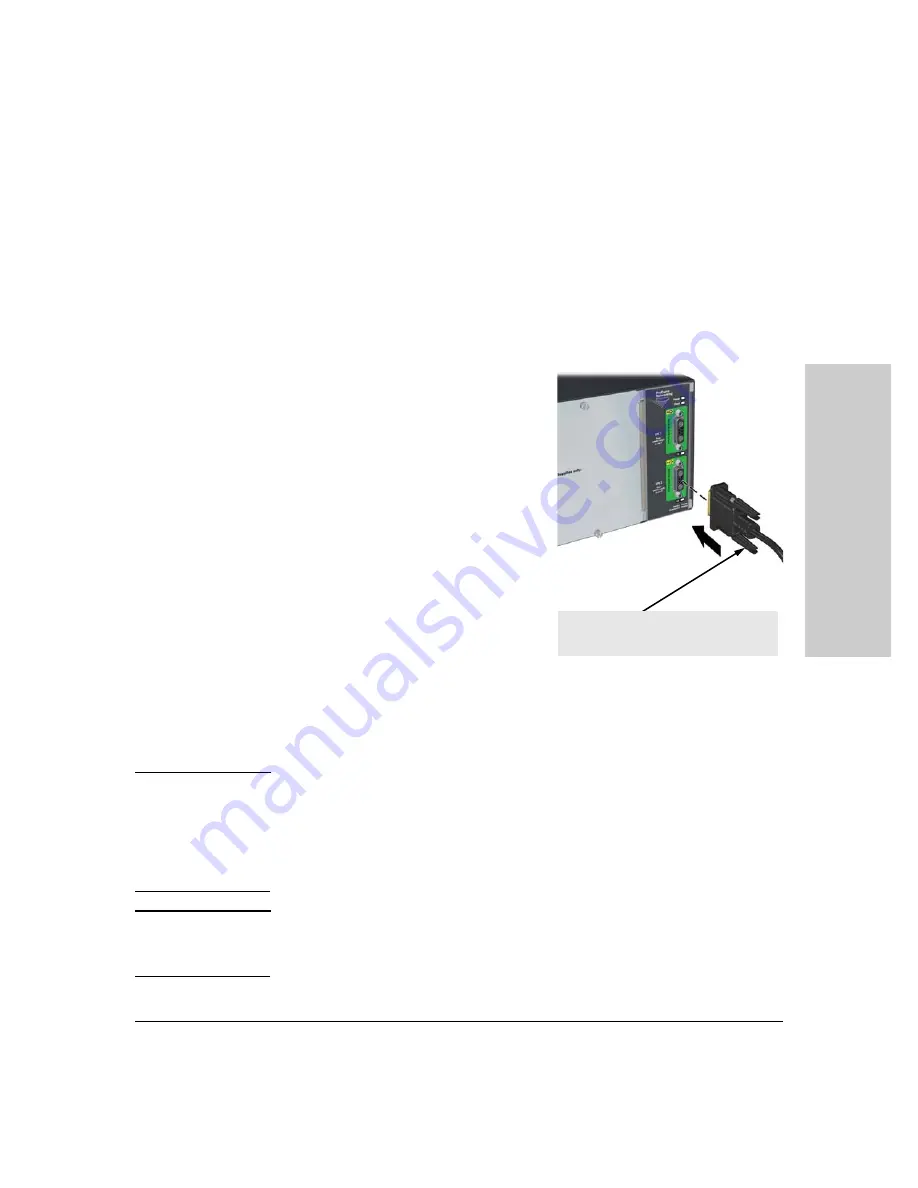
Connecting EPS Ports to Switches
To connect:
Push the EPS cable plug into the desired
port until the thumb screws engage with
the screw holes in the unit. Tighten the
thumb screws.
Always attach the EPS cable to the
connector that is associated with an
installed power supply. For example, if
there is a power supply installed in slot 1,
connect the EPS cable to EPS 1.
When power is on for the Power Supply
Shelf and for the connected switch, the
Device Connected LED should go on to
confirm a powered-on switch is at the
other end of the cable.
If the Device Connected LED does
not
go
on when the cable is connected to the port, see Diagnosing with the LEDs in
chapter 3, “
.”
To disconnect:
Unscrew the thumb screws on the plug and pull the plug out of the port.
C a u t i o n
Disconnecting the EPS (PoE power) cable with power flowing is not
supported, and could cause loss of PoE power to all network devices
connected to the switch. The Power Supply Shelf must be powered down
before disconnecting the EPS (PoE power) cable, if power is flowing. Only
the power supply to be disconnected must be powered down. The EPS cable
may be connected at any time.
N o t e
Refer to
“EPS Port Operation” on page 1-5
for detailed information and on PoE
power usage, and to
for information on maximum
available PoE power.
EPS Connector:
• Only use the cables supplied with the unit