800.338.3884 • procaresoftware.com
2
Connect Network Door Controller
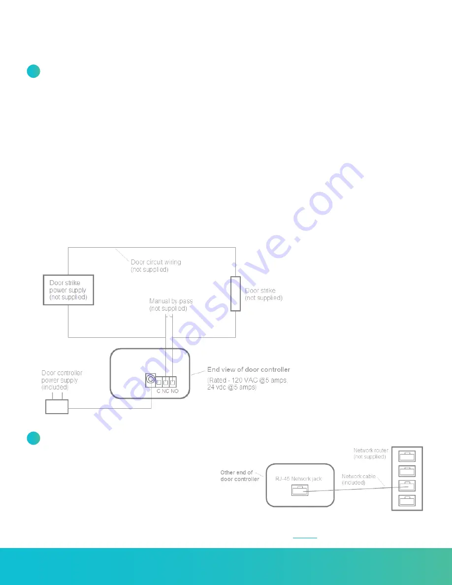
Connect to Your Router
Connect the other end of the Door Controller to an open
port on your router using the network cable (included)
or your own CAT5 / RJ-45 network cable (diagram “B”).
The green (side) light should no longer be lit (it will stop
flashing) and a solid orange light should appear on the
RJ-45 connection, indicating it is connected to your
network. A yellow flashing light indicates network traffic.
See Indicator Lights (page 1).
DIAGRAM A
END VIEW OF DOOR CONTROLLER
DIAGRAM B
OTHER END OF DOOR CONTROLLER
Connect to Your Electrically Operated Door
The Door Controller is designed as a switch for controlling an electrically operated door strike (not supplied).
a.
Attach one wire from the Door Strike circuit to the Common (C) terminal (as shown in diagram “A”).
b.
Attach the other wire to:
• For an electric door strike: Connect to the Normally Open (NO) terminal (as shown in diagram “A”).
• For a magnetic lock: Connect to the Normally Closed (NC) terminal.
(Note: Diagram “A” shows a “NO” connection. Change to a “NC” connection for a mag. lock).
NOTE:
A manual bypass is strongly recommended so a staff person may open the door as needed.
c.
Plug the Door Controller into a standard 110 VAC wall outlet. Use of a surge protector is strongly recommended.
• The red power indicator light should come on (side of Door Controller). See Indicator Lights (page 1).
• A flashing green light indicates it is not yet connected to the network, which is normal at this point.
NOTE:
You’ll need a separate power supply for your electrically operated door.
1
2
If connecting to your router is not feasible,
see article
at ProcareSupport.com.


