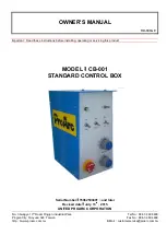
1.1 CONTROL PANEL
Front Panel
:
E-Stop
:
Emergency stop button
PB 1
:
Push Button and Power ON signal
S 2
:
Weld / Test mode selection switch
S 3
:
Auto / Manual mode selection switch
S 4
:
Clockwise / counter clockwise selection switch
S 5
:
Weld/rapid speed selection switch
VR1
:
Welding speed adjustment
VR2
:
Welding timer adjustment
Rear Panel
:
SW1
:
Power switch
SW2
:
Voltage selection switch
F1
:
Fuse(1A)
CM1
:
Motor connector (2Pin)
CM3
:
Foot switch connector (3Pin)
CM4
:
Welding source connector (4Pin)
1
Summary of Contents for 15062500401
Page 2: ......
Page 5: ...T T TH H HI I IS S S P P PA A AG G GE E E I I IS S S B B BL L LA A AN N NK K K i ...
Page 12: ...4 1 CONTROL SYSTEM 7 ...
Page 13: ...4 2 WIRING DIAGRAM 8 ...


