


WHEEL-E usage instructions
17
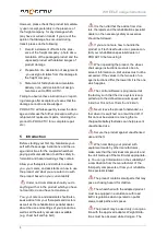
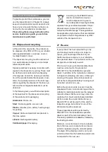
The
height of the parking stand
is adjusted
by unscrewing the M6 oval head screw (AF
4 mm) with the radius disc and repositioning
the adjustment inlet along the specified row of
holes in the parking stand and inlet. Finally,
retighten the M6 oval head screw (AF 4 mm)
up to 11 Nm of torque.
Figure 16: M6 oval head screw with radius disc and
adjustment inlet to adjust the height of the parking
stand
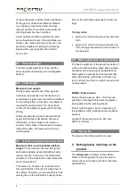
Information when equipping with manoeu-
vring rollers:
After adjusting the height of the
parking stand, the manoeuvring roller must be
positioned in the active position outside on the
parking stand.
20.2 Steering column and handlebar
20.2.1 Seat and handlebar position
The seat position and therefore the handlebar
position depend on the upper-body stability or
the torso musculature. A suitable adjustment of
the steering column to the arm length will have
been made during the consulta-
tion/measurement procedure.
With weak torso musculature
, the handlebar
position should generally be chosen so that the
upper body stays in an upright position when
reaching for the handlebar while driving.
Movement of the upper body or head to the
front and back should be avoided if possible. In
this case, a slightly higher handlebar position is
selected (chest height or higher).
For active users with corresponding torso
stability
, a lower handlebar position can be
selected (chest height or lower).
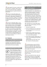
The following points must be fulfilled for the
proper seating position:
The handlebar (including the installed fit-
tings) may not touch the knees or thighs
when steering. The steering movement
may not be blocked by the knees or thighs.
The elbows should not be completely ex-
tended when the steering bar points com-
pletely forward away from the body.
At the maximum steering angle to the right
and to the left, the elbows should not be
completely locked.
A suitable restraint system must be used
if you have poor seating stability due to a lack
of or weak core strength. The selection of the
suitable system must be made in conjunction
with your doctor or therapist and/or defined
and implemented by your rehabilitation special-
ist dealer. There are various systems available
such as chest straps or four-point safety belts.
Rehabilitation specialist dealers can also often
create a customised system or adapt commer-
cially available systems.
Recommended equipment:
PRO ACTIV also offers restraint systems such
as hip straps with belt and Velcro fastener and
chest straps of various lengths.
20.2.2 Adjustment of the handlebar posi-
tion
The following instructions are intended
for and may only be carried out by a rehabilita-
tion specialist dealer or PRO ACTIV
The handlebar
angle and height can be ad-
justed
:
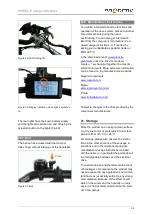
The
angle
is adjusted at the top fork
bridge. To do this, loosen the four M6
clamp screws (AF 5 mm) on the clamp
slightly so that the steering column's angle
can be adjusted using minimal force. The
angle adjustment is continuous (as a
guide, there is a 12° scale fitted). When
M6 oval head
screw with
radius disc
Adjustment
inlet with
manoeuvring
rollers


